Product Support
Select your product below for product specific support.
Access the latest User Manual, Firmware, Tech Notes and FAQs.


Retired Products

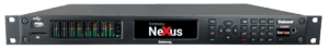
Genie Distribution
Discontinued 2020

Genie Distribution with WheatNet-IP
Discontinued 2020

Merlin PLUS
Discontinued 2020
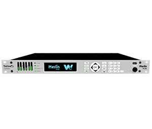
Merlin PLUS with Wheatnet-IP
Discontinued 2020
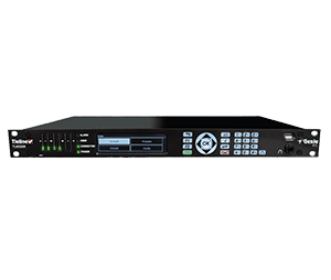
Genie STL
Discontinued 2020
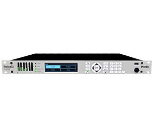
Merlin
Discontinued 2020

Bridge-IT XTRA
Production Ended 2021
No Repairs, Servicing Phone or Email Support Available from 12th October 2025

Bridge-IT
Production Ended 2021
No Repairs, Servicing Phone or Email Support Available from 12th October 2025
Unsupported Products
The following retired products are no longer supported due to their age and components going end-of-life.
No Repairs or Servicing
This section will list retired products that can no longer be repaired or serviced but email and phone support is still available
N/A
No Repairs, Servicing, Phone or Email Support
Clicking a codec image below will take you to a page with the limited support documentation and FAQ’s available. You will be required to create a website member’s account to access this information.
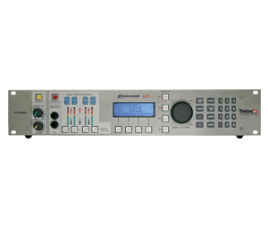
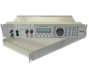
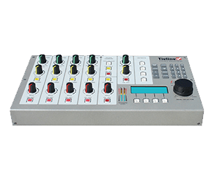
Our G3 Range of Products including Toolbox and the Software Codec Controller.
From July 1st 2024. No further support, spare parts, accessories, servicing or software can be provided.
Discontinued in 2018

Bridge-IT and Bridge-IT XTRA
Production ended 2021
From April 30th 2025: No further spare parts, accessories, servicing or software can be provided
From October 12th 2025: No further Phone or Email support can be provided.
Our original audio codec line before IP Streaming connected over ISDN or POTS lines only.
Discontinued in 2002
There are no manuals, documentation, parts or support available for any of the products listed below.
- I-Mix
- Patriot
- Commander
Our Audio and Video Solutions included Switchers and Audio Distribution Amplifiers sold mainly to the Australian Market.
There are no manuals, documentation, parts or support available for any of the products listed below.
AC200, AC400, ADA500, ADA600, ADA600XLRIF, ADA800, AGA200, AS400, AS450, AS450XLRIF, AS800, AS850, AS850XLRIF, CBG100, DL100, HPA6X1B, HPA10X1B, HPA12X1B, LIU212, MA111, MA200, PFA200, PFA300, PLM200, RC800, RF300, SVDA600, SVS450, VADA300, ADA1010, VAM400, VAS300, VAS850, VASS10, VDA10, VDA20, VDA300, VDA600, VS450, VS850, VWU200
Our Analog Broadcast Mixers sold only in the Australian Market.
There are no manuals, documentation, parts or support available for any of the products listed below.
- Brolga (BM100)
- BM200
- BM210
- BM212
Test Lines
Testing IP Connections and Port Forwarding
If you are on a public static IP address you can dial a Tieline test codec on one of the following public IP addresses to test your IP codec
Default Tieline Ports | ||
Application | Session Port | Audio Port |
IP1 | TCP 9002 | UDP 9000 |
IP2 | TCP 9012 (G3 codecs) | UDP 9010 |
Tieline ToolBox & TLG3GUI | UDP 5550 | |
SIP | UDP 5060 | UDP 5004 |
USA IP Codec Test Numbers
- 50.212.142.1 = Gateway
- 50.212.142.2 = Bridge-IT XTRA
- 50.212.142.3 = Bridge-IT II
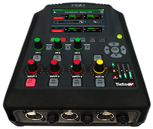
- 50.212.142.4 = ViA
- 50.212.142.5 = MPX
- 50.212.142.6 = Audio & GPIO/LIO Loopback test
Australian IP Codec Test Numbers
- 203.38.199.161 = Gateway 4 (LAN Port 1)
- 203.38.199.165 = Gateway 4 (LAN Port 2)
- 203.38.199.163 = Genie Distribution (LAN Port 1)
- 203.38.199.164 = Genie Distribution (LAN Port 2)
- 203.38.199.166 = Merlin PLUS (LAN Port1)
FAQs
See below for General Frequently asked questions.
For more product specific FAQs please select your product from the above list
You can make IP connections to other manufacturer’s codecs if the SIP protocol is used on both ends and the codec you are connecting to is EBU N/ACIP Tech 3326 compliant. The following parameters will need to be set on both codecs. Try the following setting, once connected; you can try other settings as desired.
- Profile mono
- Bit rate 64k
- Algorithm G.722
- Session port 5060 TCP
- Audio port 5004 UDP
On the newer firmware versions of Bridge-IT, Merlin, and Genie codecs the SIP feature will need to be enabled. Using the HTML 5 GUI go to Transport > SIP Interfaces and select Enable.
Below are links to information about compatibility to other manufacturer’s codecs using SIP and ISDN for the G5 family of codecs including the Merlin and Genie codecs as well as the G3 family of codecs.
Management Information Base (MIB) files are required for SNMP applications to interact with your Tieline codec and interpret SNMP data. The codec supports SNMPv1 and SNMPv2 MIB protocols.
The required MIB files can be downloaded from the codec using the following link in a PC web browser connected to the same network as your codec:
http://<your_codec_address>/mibs/tieline-mibs.zip
Save the .zip file to your PC and import the contents into the MIB browser you use to manage SNMP-enabled network devices.
Important Note: The codec supports the attributes specified in the MIB-II standard.
Please verify that your SNMP software contains the required files as specified in
RFC 1213
The following 10 tips are provided to help obtain the best possible IP connection between two codecs, without paying for QoS (Quality of Service). Note: Please ensure you select the correct country setting when creating 3G profiles using Toolbox.
1) Always use the best quality Internet Service Provider (ISP). Tier 1 service providers are best as their infrastructure actually makes up the Internet ‘backbone’. Wikipedia lists the major service providers that make up the Internet backbone at: http://en.wikipedia.org/wiki/Internet_backbone. In Australia Telstra is equivalent to one of these service providers.
2) You will get the best quality connection if both the local (studio) and remote codecs use the same Internet service provider. This can substantially increase reliability, audio bandwidth and reduce audio delay. Using the same service provider nationally can give better results than using different local service providers. This is especially true if one of the service providers is a cheap, low-end domestic service provider, which buys its bandwidth from other ISPs. Second and third tier providers sublease bandwidth from first tier providers and can result in connection reliability issues due to multiple switch hops. We also highly recommend using First Tier ISPs if connecting two codecs in different countries.
3) Sign up for a business plan that provides better performance than domestic or residential plans. Business plans typically have a fixed data limit per month with an additional cost for data beyond that limit. In addition, Service Level Agreements (SLA) will often provide better support and response times in the event of a connection failure. Domestic plans are often speed-limited or “shaped” when usage exceeds a predefined limit. These plans are cheap but they are dangerous for streaming broadcast audio.
4) Ensure that the speed of the connection for both codecs is adequate for the job. The minimum upload speed recommended is 256 kbps for a studio codec and 64 kbps for a field unit connection.
5) Use good quality equipment to connect your codecs to the Internet. (Tieline successfully uses Cisco®[1]switching and routing equipment.):
- If you are using a DSL or ADSL connection make sure you purchase a high quality modem that can easily meet your speed requirements. This is especially important if you are over 4 kms from an exchange.
- If you have multiple codecs connected to a local area network (LAN) please ensure that your network infrastructure is designed for media streaming and not domestic usage. Tieline has tested several cheap 8-port switches that lose more packets between local computers than an international IP connection between Australia and the USA!
Please Note: You should be able to stream audio between two codecs on your LAN and get ‘link quality’ readings of L99R99. If you see anything less than this then you should get a network engineer to investigate the issue.
If using a wireless connection ensure that the antenna signal strength received is strong. The type of antenna used and the amount of output gain also affects connection quality.
- If you are using a 3G phone please make sure the battery is fully charged and that you are close to a cell-phone base station.
6) Once your Internet connection is installed at the studio check that the connection performance is approximately what you ordered and are paying for. A connection can perform below advertised bit rates if:
- There is an error in ISP configuration;
- There is an error in modem configuration;
- There is a poor quality line between the studio and the exchange;
- There are too may phones or faxes connected to the phone line; or
- Line filters have been connected incorrectly.
You can test the Internet connection speed by connecting a PC to the Internet and using http://www.speedtest.net/index.php. If the bandwidth detected is low then something is wrong. Get it fixed before going live!
7) Use a dedicated DSL/ADSL line for your codecs. Do not share a link with PCs or company networks. The only exception to this rule is if an organisation has network equipment and engineers that can implement and manage quality of service (QoS) on its network.
8) Use UDP as the preferred audio transport protocol. TCP generally results in lower bitrates and random drop-outs of audio over the Internet. Only use TCP if UDP is blocked by firewalls and you are unable to connect.
9) When using UDP ensure the total bit rate (audio bit rate plus header bit rate) is no more than 80% of the ISP connection rate. IP headers require around 20 kbps in addition to the audio bit rate. For example, with a 64 kbps connection the audio bit rate should be (64-20) x 0.8 = 31.2 kbps or lower. For TCP we suggest a limit of 50% or less.
10) Wireless IP connections can easily become congested and result in packet loss and audio drop-outs. It is very difficult to guarantee connection quality when there is no way of knowing how many people are sharing the same wireless connection. Examples of wireless connections include:
- WiFi connections within your LAN (These are unmanaged connections and should not be used to distribute audio when setting up IP connections);
- GSM CSD and HSCSD connections; and
- EV-DO, 3G UMTS or HSDPA phone connections.
Note: Be careful when using cell-phone connections at special events where thousands of people have mobile phones. This can result in poor quality connections and audio drop-outs if cell-phone base stations are overloaded. The “Ss” wireless signal strength reading on the codec screen should be between 4 and 9 to connect reliably.
Complete the following check list and aim for a score of at least 8 out of 10 before going live.
Number | Check | Result |
1 | Using a reputable Tier1 ISP that’s part of Internet backbone. | |
2 | The same ISP is being used for both codec connections. | |
3 | The ISP Plan is a Business Plan or equivalent. | |
4 | The ISP connection speed is adequate (256 kbps or higher). | |
5 | Equipment is high quality and suitable for media streaming. | |
6 | The ISP connection speed has been tested and is suitable. | |
7 | The ISP connection is not shared with PCs or other devices. | |
8 | UDP is being used as the audio transport protocol. | |
9 | Only up to 80% of ISP connection bandwidth is being used. | |
10 | There are no wireless connections being used. |
Forward Error Correction is designed to increase the stability of UDP/IP connections. It is configurable for UDP data streams only. Both the local and remote codec FEC settings can be configured before dialing and ‘on the run’ when the codecs are connected.
Important Note: FEC can only be programmed for use with the Music, Music Plus and Voice G3 algorithms. FEC is only a benefit if link quality (LQ) displayed on your codec is below “L99 R99”.
Understanding DSL (ADSL) and FEC
In general, the higher the bit rate you require for a codec’s IP connection, the more likely it is that you will encounter connection instability. The relationship between the codec connection bit rate and your broadband uplink speed is useful to help you choose the IP settings you should use for different IP profile connections.
The way FEC works is by sending a secondary stream of audio packets so that if your primary audio packets are lost or corrupted, then packets from the secondary stream can be substituted to correct the primary stream. The amount of FEC that you require is will depend on how many data packets are being lost over the network connection.
As an example of how FEC works, if you have a FEC setting of 20% and you are losing one packet in every five that is sent, this packet will be replaced by FEC to maintain the quality of the connection. If you are losing more packets than this, say one in three, it will be necessary to increase the FEC setting to 33% to compensate.
Please note: There is an inverse relationship between FEC settings and the jitter-buffer millisecond setting that you use for IP connections.
So why not use 100% FEC every time? The answer is because you need twice the bit rate to achieve full redundancy and depending on the link conditions, this could potentially cause more dropouts because of network congestion than it fixes. Here is a simple rule to remember: Your maximum uplink speed is all the bandwidth you have to play with. As a rule of thumb, try not to exceed more than 80% of your maximum bandwidth. If your link is shared, be even more conservative.
You should also consider the remote end too. What is their maximum upload speed? Is the connection shared at either end? Your bit rates, FEC settings and buffer rates must be pre-configured at both ends before you connect therefore so it’s always better to set your connection speed and balance your FEC according to the available uplink bandwidth at each end for best performance.
FEC Setting | Bitrate Ratios | Connection Use |
100% (Lowest delay) | A simultaneous dual-redundant stream (1:1 ratio) is sent from the codec. Twice the connection bit rate is required to operate the codec using the 100% setting. For example, if your connection is at a bit rate of 14,400, you will require an additional 14,400 kilobytes of bandwidth to allow for the FEC data stream – a total of 28,800. | Recommended to be used over wireless and international connections. |
50% | Additional data is sent by FEC in a ratio of 2:1. | Recommended to be used over international & national connections |
33% | Additional data is sent by FEC in a ratio of 3:1. | Recommended to be used over national and local connections. |
20% (Highest delay) | Additional data is sent by FEC in a ratio of 5:1. | Recommended to be used over local and LAN connections. |
Off | FEC is off in the codec and the connection bandwidth is equal to the connection bit rate setting in the codec. | Recommended to be used over wired LAN connections as well as managed T1 & E1 connections for STLs that have connections that aren’t shared & have quality of service (QOS). |
Calculating FEC Bandwidth Requirements
As an example, if you want 15 kHz mono (using the Tieline Music Algorithm) you will need at least a 24kbps connection for audio. Adding 100% FEC will add another 24kbps making your bit rate 48kbps plus some overhead of around 10kbps. If you’re on a 64kbps uplink, you should consider reducing your FEC or switching to a 7kHz audio link at 14.4kbps with the Voice G3 algorithm and 100% FEC
Here is another example, if you want 15 kHz stereo, you need at least 56kbps for the audio. 100% FEC requires at least 112kbps and 50% FEC requires at least 84kbps. If your uplink speed is 256kbps and you’re on a shared connection, then choosing a lower FEC% of 20%-33% may give you better results.
Conserving Bandwidth with FEC
As mentioned previously, there is a trade-off between the quality and the reliability of an IP connection – particularly when FEC is activated on your codecs. However, it is possible in certain situations to set different FEC on the remote and local codecs to conserve bandwidth and create more stable IP connections.
For example, if your broadcast is a one-way broadcast from a remote site, i.e. you are not using the return path from the studio, or only using it for communications purposes, it is possible to reduce or turn off FEC at the studio codec. This effectively reduces the bandwidth required over the return link (communications channel) and increases the overall bandwidth available for the incoming broadcast signal from the remote site. This could be particularly useful if you have limited uplink bandwidth at the remote location.
Keep in mind that as you move from local to national to international connections, you should be more conservative with your FEC and connection rates.
Most PCs contain software that is scheduled to run at regular intervals. For example, virus scanners download new definitions every day or so, email programs usually check for mail every five minutes – and let’s not forget those regular Windows updates. In addition, the time clock in a PC is synchronized, so activities from many PCs transferring small amounts of information can accumulate at points in time – causing more traffic and increasing the potential for drop-outs in audio.
It is very hard to determine which PCs will be using what data at any point in time. As a result, we highly recommend installing a dedicated internet connection for your broadcast codec, or engage the services of an IT company to configure your network for Quality of Service (QoS). This will ensure your codec data traffic has priority over PC data traffic.
If your codecs have a dedicated connection and you are still experiencing drop-outs, see if you can link them to a certain time of the day. On some cheap residential unlimited data plans, the availability of data is limited by the number of users connected at a point in time. Peak times like when children get home from school can bring reduced bandwidth.
If your service provider is providing a residential plan with contended bandwidth then ask for a business plan where bandwidth is not contended. A contended plan will usually limit bandwidth to users as demand increases. It is also a good idea to ensure both ends of a codec connection are with the same service provider.
Link Quality (LQ)
Use the LQ (Link Quality) numbers on your codec to determine the magnitude of any data problem. Return (Local or “L” on a G3 codec) and Send (Remote or “R” on a G3 codec) LQ numbers can also help you to determine if the problem is occurring at both ends of the connection or only one.
For example, on an IP connection the Return (or “L” on a G3 codec) reading represents the audio being downloaded from the network locally (i.e. audio data is being sent by the remote codec). Conversely, the Send (or “R” on a G3 codec) link quality reading represents the audio data being sent by the local codec (i.e. being downloaded by the remote codec).
Important Note:
- The Return link quality reading is exactly the same as the Local (L) setting displayed on a G3 codec.
- The Send link quality reading is exactly the same as the Remote (R) setting displayed on a G3 codec.
Wireless Connections
If you are connecting over wireless IP, start with a conservative bit-rate setting of 24Kbps, and then see how the network performs at this bit-rate. We do not recommend connecting immediately at higher bit-rates of say 64-128Kbps over 3G networks until you are sure your network will support these data rates. It is a case of trial and error and the data rates supported will often vary greatly from region-to-region, and even from day-to-day. In addition, the “Ss” wireless signal strength reading on the codec screen should be between 4 and 9 to connect reliably.
Forward Error Correction
Tieline IP audio codecs are designed to provide error concealment and can also implement Forward Error Correction (FEC), which is designed to increase the stability of UDP/IP connections in the event that data packets are lost.
FEC works by sending a secondary stream of audio packets over a connection so that if your primary IP audio stream packets are lost or corrupted, then packets from the secondary stream can be substituted to replace them. The amount of FEC required depends on the number of data packets lost over the IP connection. Both the local and remote codec FEC settings can be configured in Tieline IP codecs before dialing. These settings can also be changed ‘on the run’ while the codecs are connected. FEC should only be used if link quality displayed on the codec is below L:99 R:99, as it is of no benefit otherwise.
What’s sort of IP addresses are available?
An IP address is a unique number that allows your IP codec to communicate over IP networks and the internet using the Internet Protocol standard. There are two types of IP addresses – public and private.
Internet Service Providers (ISPs) can allocate either a DHCP allocated or static public IP address to allow network devices to communicate with each other over the Internet. ISPs usually allocate dynamically (automatically) assigned public IP addresses to allow network devices to communicate with each other over the Internet. These are not recommended for studio installations because each time you connect to your ISP the IP address of your studio codec can change. You can also request a static public IP address from your ISP, which always stays the same, and this makes it easier to call the studio from your remote sites.
If you connect your codec to a private IP network that is behind a router and firewall then by default you will normally be allocated a private IP address for your codec. This is a bit like a private extension behind a PABX phone system – it’s easy to call out, but more difficult to call in directly.
Recommended IP address configuration for codecs on private IP networks
When you setup your studio codec for IP connections it is best to program a static IP address so that codecs dialing into it can always rely on the address being the same. If you are connected to a router that allocates private IP addresses behind a firewall then the router can allocate a static or DHCP dynamically allocated address.
Static private IP addresses can cause DNS server connection issues but DHCP addresses have “lease times”, which means they are renewed on a regular basis and can change. However, it is also possible to permanently extend the lease time within a router for DHCP allocated addresses. The best way to program your router is to perform the following:
- Allocate a ‘permanently leased DHCP private IP address’ to the codec. In effect this is like a static IP address. To do this, go to the DHCP server configuration section within your router’s programming interface and program the router to allocate a permanently leased, but DHCP allocated IP address to the codec – based on the codec’s MAC address (which can be found via Menu > Unit Details in Commander and i-Mix codec menus, or via Config > Unit in Bridge-IT codecs.).
- Ensure that TCP port 9002 and UDP port 9000 are open in your firewall to ensure that audio and other essential codec data packets can easily traverse the networks between your studio and remote codecs.
If you have several codecs in your network connected to a local LAN you will probably also find it is much easier to manage all your codec IP addresses based on the preceding steps rather than programming each codec independently.
In summary…
In summary – we recommend using a dedicated DSL connection at the studio for broadcasting over IP – preferably with a static public IP address when possible. If for practical reasons you are using a router and your codec has a private IP address, ensure that your IT administrator allocates a permanently leased, but DHCP allocated IP address based on the MAC address of your codec. Open UDP port 9000 and TCP port 9002 to allow the safe passage of audio and codec data through your firewall and you will be setup in the most appropriate way for reliable IP broadcasting!
Can't Find what you are looking for?
- All trademarks mentioned belong to their respective owners and are used for reference only
- Errors and Omissions Excepted
- All information is subject to change without notice.