Data must be enabled to activate contact closure operation and RS232 data. The codec supports both in-band and out-of-band data depending on the algorithm you are using. In-band RPTP data is automatically enabled when using the Tieline Music or MusicPLUS algorithms over IP. It is also possible to enable synchronized out-of-band data using any algorithm via the RS232 data port on the codec.
Algorithm Selected |
IP |
Tieline Music and MusicPLUS |
•In-band RPTP data is enabled automatically •Synchronized out-of-band data can be enabled and disabled as required •Using out-of-band data with rules between G5 codecs employing relay reflection minimizes latency •These algorithms must be used when connected to G3 codecs as they don't support out-of-band data |
All other algorithms |
•No in-band data available; synchronized out-of-band data can be enabled and disabled |
Select Enable Auxiliary Data when creating a program in the Program Manager panel to enable RS232 data and activate rules employing relay reflection over a connection. This will allow the codec to connect to external devices and send RS232-compatible data via the serial port on the rear panel. Alternatively, enable auxiliary data using the Setup menu as follows:
1.Press the HOME  button to return to the Home screen.
2.Use the navigation buttons on the front panel to select Connect and press the  button.
3.Select IP and press the  button.
4.Select Tieline (or Sessionless and then Peer-to-Peer) and press the  button.
5.Use the down  navigation button to select Setup and press the
  button.
6.Navigate to Data and press  to toggle between Enabled and Disabled (Note: default setting is Disabled).
Configuring Control Port Contact Closure Operation
The Rules panel in the Web-GUI can be used to configure switch inputs and relay outputs. Codec 'rules' configure events based on specific codec actions. Typically rules are based on a change in the state of a physical CONTROL PORT GPIO, or a WheatNet-IP logic IO, or a codec program being connected or disconnected. Rules can only be created with the Web-GUI while the codec is disconnected. There are two ways to create rules in the HTML5 Toolbox Web-GUI:
1.The Rules panel, or
2.The Program Manager panel.
Rules for connecting or disconnecting a program are configured in the Rules panel. Rules for connecting or disconnecting an audio stream are configured in the Program Manager panel.
|
Important Note: A non-WheatNet-IP Tieline codec can be configured to trigger a logic IO in a Tieline WheatNet-IP codec. Up to 64 logic IOs are available in Genie Distribution and Merlin PLUS WheatNet-IP codecs, as well as 4 physical CONTROL PORT GPIOs. |
About Relays
Bridge-IT XTRA has four CMOS solid state relays for the control of equipment, consisting of four relay closures and four opto-isolated outputs.
Inputs
The input signal is referenced to chassis ground, i.e. the ground reference terminal on the terminal block is connected the chassis. The input device is a high impedance CMOS device with a 330 ohm pull-up resistor to +5 volts.
Operation is as simple as joining the input pin to the ground terminal. This can be via a remote relay contact or the open circuit collector of a transistor or FET. DO NOT feed voltages into the inputs.
Outputs
CMOS field effect transistors switch a low impedance path between the two pins when activated. These are opto-isolated and floating above ground. It is important to current-limit the source as damage will result where the current exceeds 100mA peak-to-peak. No more than 48 volts peak-to-peak should be used as a safety precaution. The resistance of the CMOS element is approximately 25 ohms in the ON state.
Control Port Pin-outs
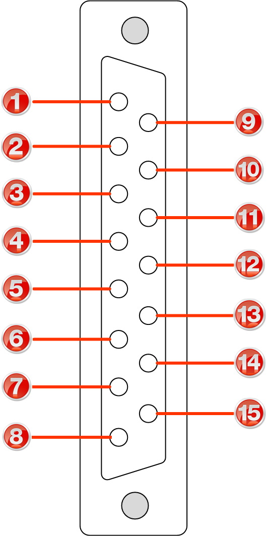
A closing contact across Inputs 1-4 to Ground will provide a closing contact on the remote codec Outputs 1 to 4. If your codec supports multi-unicast connections to multiple codecs, a contact closure will appear on each of the compatible (non-G3) remote codecs' corresponding contacts. I.e. Input 1 shorted, Output 1 contacts on all connected codecs closed.
 Female DB-15 Codec Connector |
|
|
Important Note: For more information about how to configure relay operations with a PC using HTML5 Toolbox web-GUI, please see the sections titled "Creating Rules". |
RS232 Pin-outs and Data Connections
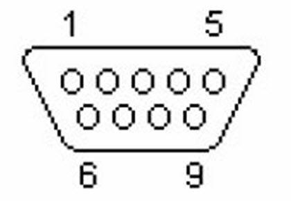
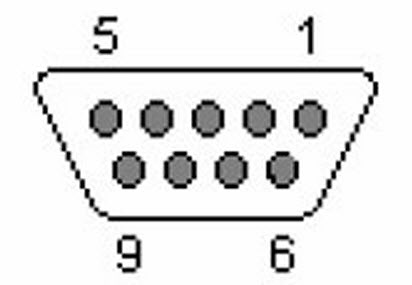
Pin |
INTERFACE Female DB9 (RS232) DCE |
DATA Male DB9 (RS232) DTE |
1 |
No Connection |
No connection |
2 |
TX Data |
RX Data |
3 |
RX Data |
TX Data |
4 |
No connection |
No connection |
5 |
Signal Ground |
Signal Ground |
6 |
No Connection |
No connection |
7 |
CTS |
RTS |
8 |
RTS |
CTS |
9 |
No connection |
No connection |
 DB9 Male Connector Pins |
 DB9 Female Connector Pins
|
|
Important Notes: •When connecting to G3 codecs only in-band data is available via the Music and MusicPLUS algorithms. •Codecs using Bridge-IT firmware lower than v2.8.xx cannot activate relays on Tieline G3 codecs or send RS232 data to them. •It is important that you enable serial port flow control within the codec. Flow control regulates the flow of data through the serial port. If disabled, data will flow unregulated and some may be lost. •Ensure you match the serial port baud rate to match the rate of the external device you are connecting to. Ideally the settings on both codecs should match, or you could have data overflow issues. •Only the dialing codec needs to be configured to send RS232 data. Session data sent from the dialing codec will configure all other compatible codecs (non-G3) you connect with. •RS232 data can be sent from the dialing codec to all end-points of a multi-unicast connection. Note: Bidirectional RS232 data is only available on the first connection dialed when multi-unicasting. |

