Relays
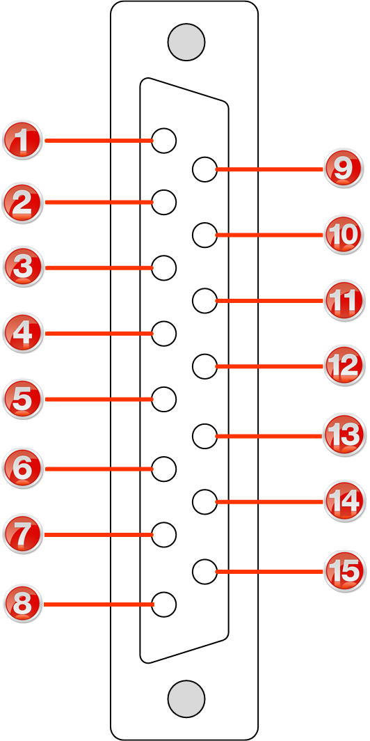
The codec uses a DB15 connector to facilitate use of four CMOS solid state relays for the control of equipment, consisting of four relay closures and four opto-isolated outputs.
Inputs
The input signal is referenced to chassis ground, i.e. the ground reference terminal on the connector is connected the chassis. The input device is a high impedance CMOS device with a 330 ohm pull-up resistor to +5 volts.
Operation is as simple as joining the input pin to the ground terminal. This can be via a remote relay contact or the open circuit collector of a transistor or FET. DO NOT feed voltages into the inputs.
Outputs
CMOS field effect transistors switch a low impedance path between the two pins when activated. These are opto-isolated and floating above ground. It is important to current-limit the source as damage will result where the current exceeds 100mA peak-to-peak. No more than 48 volts peak-to-peak should be used as a safety precaution. The resistance of the CMOS element is approximately 25 ohms in the ON state.
Control Port Pin-outs
A closing contact across Inputs 1-4 to Ground will provide a closing contact on the remote codec Outputs 1 to 4. If your codec supports multi-unicast connections to multiple codecs, a contact closure will appear on each of the compatible (non-G3) remote codecs' corresponding contacts. I.e. Input 1 shorted, Output 1 contacts on all connected codecs closed.
 Female DB-15 |
|
|
Important Note: For more information about how to program relay operations with a PC using the Toolbox Web-GUI, please see Creating Rules. |
RS232 Pin-outs and Data Connections
Pin |
INTERFACE Female DB9 (RS232) DCE |
DATA Male DB9 (RS232) DTE |
1 |
No Connection |
No connection |
2 |
TX Data |
RX Data |
3 |
RX Data |
TX Data |
4 |
No connection |
No connection |
5 |
Signal Ground |
Signal Ground |
6 |
No Connection |
No connection |
7 |
CTS |
RTS |
8 |
RTS |
CTS |
9 |
No connection |
No connection |
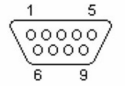
 DB9 Male Connector Pins |
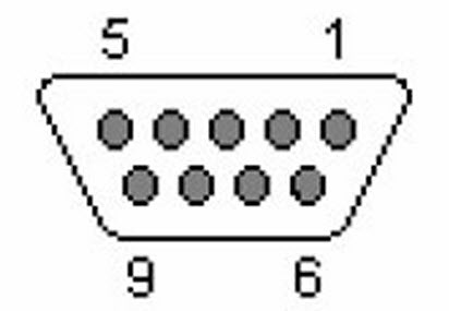
 DB9 Female Connector Pins
|
|
Important Notes: •When connecting to G3 codecs over IP, ISDN or POTS, only in-band data is available via the Music and MusicPLUS algorithms. •It is important to enable serial port flow control as it regulates the flow of data through the serial port. If disabled, data will flow unregulated and some may be lost. •Ensure you configure the serial port baud rate to match the setting of the external device to which you are connecting. Ideally the settings on both codecs should match, or you could have data overflow issues. •Only the dialing codec needs to be configured to send RS232 data. Session data sent from the dialing codec will configure all other compatible codecs (non-G3) when you connect. |

