
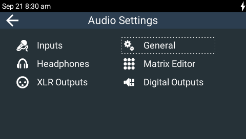
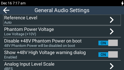
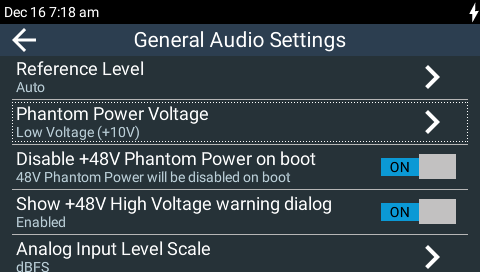
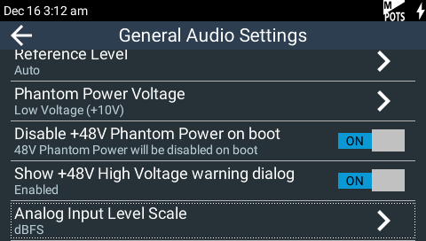
General audio settings include the following options:
•Audio reference levels.
•Phantom power voltage settings for inputs 1-3.
•Disabling +48V Phantom Power on boot.
•Show/hide +48V High Voltage warning dialog.
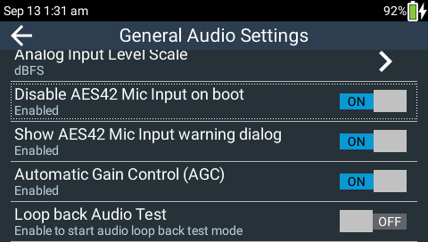
•Analog Input Level Scale adjustment.
•Disable AES42 Mic Input on boot.
•Show AES42 Mic Input warning dialog.
•Output AGC enable/disable.
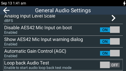
•Loopback audio test.
To adjust these settings:
1.Press the HOME ![]() button to return to the Home screen, then tap Audio
button to return to the Home screen, then tap Audio  .
.
2.Tap General  .
.
Audio Reference Levels
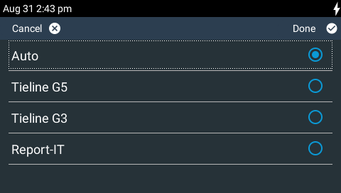
By default, codec the PPM METERS on the front of the codec, on the TOUCH SCREEN, or the HTML5 Toolbox Web-GUI, use dBFS to express nominal operating, headroom and noise floor levels. The codec can also automatically adapt to different Tieline reference scales. A Tieline codec with proprietary Tieline session data enabled will automatically adjust the reference level to suit G5 and G3 codecs, or Report-IT. When connecting to a non-Tieline codec, or a Tieline codec without session data enabled, the codec will use the Tieline G5 reference scale setting.
The default Tieline G5 audio reference scale displayed on the PPMs when you connect to a Tieline G5 codec is -38dBFS to 0dBFS (e.g. Merlin, Genie, Bridge-IT and ViA codec families). Using this reference scale audio peaks can safely reach 0dBFS without clipping, providing 18dB of headroom from the nominal 0vu point. The comparison table below outlines the reference scales for G5 and G3 codecs and Report-IT in dBFS, as well as the equivalent dBU scale.
|
Reference Setting |
Description |
dBu |
dBFS |
1 |
Tieline G5 |
PPM meter low point |
-16dBu |
-38dBFS |
Nominal 0vu reference level |
+4dBu |
-18dBFS |
||
Level at which audio will clip/distort |
+22dBu |
0dBFS |
||
2 |
Tieline G3 |
PPM meter low point |
-11dBu |
-29dBFS |
Nominal 0vu reference level |
+4dBu |
-14dBFS |
||
Level at which audio will clip/distort |
+18dBu |
0dBFS |
||
3 |
Report-IT |
PPM meter low point |
-9dBu |
-23dBFS |
Nominal 0vu reference level |
+4dBu |
-10dBFS |
||
Level at which audio will clip/distort |
+14dBu |
0dBFS |
1.Press the HOME ![]() button to return to the Home screen, then tap Audio > General > Reference Level.
button to return to the Home screen, then tap Audio > General > Reference Level.
2.Tap to select the appropriate reference scale to suit the codec to which you are connecting.
|
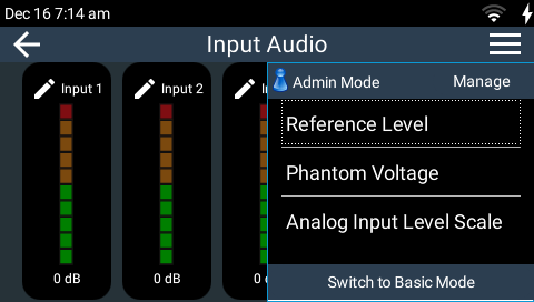
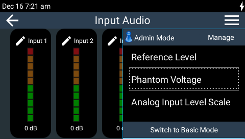
Helpful Hint: As a shortcut you can tap the Hamburger
|


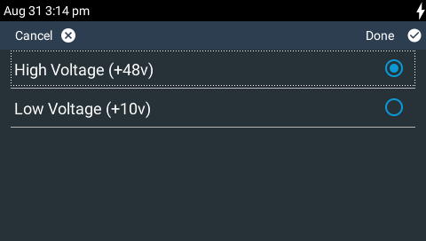
Phantom Power Voltage
|
VOLTAGE WARNING: Microphones and other ancillary audio equipment may be very sensitive to phantom power voltages and should not be attached to the codec inputs when phantom power is enabled, or equipment may be damaged these voltages. |

The phantom power voltage setting applies across inputs 1-3. However, it is possible to enable or disable phantom power on individual inputs.
1.Press the HOME ![]() button to return to the Home screen, then tap Audio > General > Phantom Power Voltage.
button to return to the Home screen, then tap Audio > General > Phantom Power Voltage.
2.Tap to select the preferred voltage setting.
|
Helpful Hint: As a shortcut you can tap the Hamburger
|
Disable +48V Phantom Power on Boot
By default, 48V phantom power is disabled when the codec is rebooted. This protects users from attaching a non-phantom device to a phantom-enabled codec input and damaging equipment. This feature can be disabled if required:
1.Press the HOME ![]() button to return to the Home screen, then tap Audio > General > Disable +48V Phantom Power on Boot.
button to return to the Home screen, then tap Audio > General > Disable +48V Phantom Power on Boot.

2.Tap the On/Off button to enable and disable this feature.
Show +48V High Voltage Warning Dialog
By default, a 48V phantom power warning dialog is displayed when phantom power is enabled in the codec. This feature can be disabled if required:
1.Press the HOME ![]() button to return to the Home screen, then tap Audio > General > Show +48V High Voltage warning dialog.
button to return to the Home screen, then tap Audio > General > Show +48V High Voltage warning dialog.
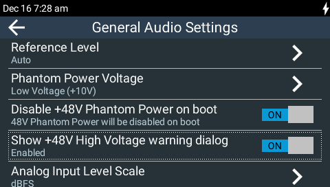
2.Tap the On/Off button to enable and disable this feature.
Analog Input Level Scale
It is possible to change the input PPM meter scale used by the codec from dBFS (default) to dBU. This is most useful when viewing PPM meters in the Inputs panel in the Toolbox web-GUI. To adjust this setting:
1.Press the HOME ![]() button to return to the Home screen, then tap Audio > General > Analog Input Level Scale.
button to return to the Home screen, then tap Audio > General > Analog Input Level Scale.
2.Tap Analog Input Level Scale to toggle between selecting dBFS and dBU input PPM scales.
Disable AES42 Mic Input on Boot
|
VOLTAGE WARNING: DO NOT attach non-digital microphones or an AES3 source to input 1 when AES42 input mode is selected, or equipment may be damaged by high voltages. |
By default, the AES42 mic Input Type option on input 1 is disabled when the codec is rebooted. This protects users from attaching a non-AES42 device to input 1 and damaging it. This feature can be disabled if required:
1.Press the HOME ![]() button to return to the Home screen, then tap Audio > General > Disable AES42 Mic Input on boot.
button to return to the Home screen, then tap Audio > General > Disable AES42 Mic Input on boot.
2.Tap the On/Off button to enable and disable this feature.
Show AES42 Mic Input Warning Dialog
By default, an AES42 warning dialog is displayed when AES42 is selected as the Input Type on input 1. This feature can be disabled if required:
1.Press the HOME ![]() button to return to the Home screen, then tap Audio > General > Show AES42 Mic Input warning dialog.
button to return to the Home screen, then tap Audio > General > Show AES42 Mic Input warning dialog.

2.Tap the On/Off button to enable and disable this feature.
Output AGC (Automatic Gain Control)
AGC is enabled by default on all outputs. AGC is independent of IGC (Intelligent Gain Control) on each input.
AGC is triggered if mixed audio signals approach -2dBFS.This is to prevent hard clipping, which would introduce excessive distortion when the summed input signals exceed the full-scale range. AGC has a very fast reaction time and will decrease high audio levels by approximately 1dB every 6.6 milliseconds, up to a maximum of 34 dB of attenuation. AGC tries to return levels to normal once the output dips below -7dBFs. This will gradually increase the levels by approximately 1dB every 33 milliseconds. To enable or disable AGC:
1.Press the HOME ![]() button to return to the Home screen, then tap Audio .
button to return to the Home screen, then tap Audio .
2.Tap General .
3.Tap the On/Off button to toggle AGC on and off.

Loopback Audio Test
Loopback Audio Test mode is used by the codec to perform an input/output loopback test of audio. E.g. Input 1 is routed to analog Output 1, Input 2 is routed to Output 2. The test remains active until it is disabled, or a connection is dialed or answered, or a new program is loaded.
1.Press the HOME ![]() button to return to the Home screen, then tap Audio .
button to return to the Home screen, then tap Audio .
2.Tap General .
3.Tap the On/Off button to toggle the Loopback Audio Test setting on and off.
The following table outlines the default matrix settings for how inputs are routed to analog outputs in loopback audio test mode.
Inputs |
Analog Output 1 |
Analog Output 2 |
1 |
|
|
2 |
|
|
3 |
|
|
Aux In Left |
|
|
Aux in Right |
|
|

