
By default, the PPM METERS on the front of the codec, or in the HTML5 Toolbox Web-GUI, use dBFS to express nominal operating, headroom and noise floor levels. The PPM meters display input audio by default when the codec is not connected and then switch to monitor decoded return program audio after making a connection.
Mono and Stereo Audio Capabilities
The codec routes input 1 directly to the left output and input 2 directly to the right output when it is not connected.
To connect in stereo select a stereo algorithm in the IP Setup menu via Connect > IP > Tieline > Setup. To connect in mono select a mono algorithm in the IP Setup menu. In mono the codec mixes both inputs 1 and 2 together.
When a Bridge-IT codec answers a mono incoming call it feeds mono audio to both the left and right analog XLR outputs, as well as the left and right AES3 outputs. Note: It is not possible to mix channels 1 and 2 into dual mono outputs.
The codec feeds both analog and digital AES audio out at all times, whether the audio source is analog or digital.
Adjusting Audio Meter Reference Scale Settings
The codec can also automatically adapt to different Tieline reference scales. A Tieline codec with proprietary Tieline session data enabled will automatically adjust the reference level to suit G5 and G3 codecs, or Report-IT, using the default Auto reference level setting. When connecting to a non-Tieline codec, or a Tieline codec without session data enabled, the codec will use the Tieline G5 reference scale setting.
The default Tieline G5 audio reference scale displayed on the PPMs when you connect to a Tieline G5 codec is -38dBFS to 0dBFS (e.g. Merlin, Genie, Bridge-IT and ViA codec families). Using this reference scale audio peaks can safely reach 0dBFS without clipping, providing 18dB of headroom from the nominal 0vu point.
|
Features |
Description |
1 |
-38dBFS |
PPM meter low point |
2 |
-18dBFS |
Nominal 0vu reference level at -18dBFS (+4dBu) |
3 |
0 dBFS |
Peaks should not exceed 0dBFS when using analog audio to prevent clipping (Note: it is impossible to exceed 0dBFS when using digital audio) |
4 |
PPM meter in clip |
PPM indication displays a solid section at the right-hand end when audio is in danger of clipping |
Bridge-IT, Genie, Merlin and ViA codecs have more audio headroom than Tieline G3 audio codecs (Commander and i-Mix G3) and Tieline's Report-IT app, therefore the audio metering reference scale needs to be adjusted when connecting to one of these products. The comparison table below outlines the reference scales for G5 and G3 codecs, plus Report-IT in dBFS, as well as the equivalent dBU scale.
|
Reference Level |
Description |
dBu |
dBFS |
1 |
Tieline G5 |
PPM meter low point |
-16dBu |
-38dBFS |
Nominal 0vu reference level |
+4dBu |
-18dBFS |
||
Level at which audio will clip/distort |
+22dBu |
0dBFS |
||
2 |
Tieline G3 |
PPM meter low point |
-11dBu |
-29dBFS |
Nominal 0vu reference level |
+4dBu |
-14dBFS |
||
Level at which audio will clip/distort |
+18dBu |
0dBFS |
||
3 |
Report-IT |
PPM meter low point |
-9dBu |
-23dBFS |
Nominal 0vu reference level |
+4dBu |
-10dBFS |
||
Level at which audio will clip/distort |
+14dBu |
0dBFS |
Configure Tieline G3 Codec Audio Reference Scales
Genie, Merlin, Bridge-IT and ViA codecs have more audio headroom than Tieline G3 audio codecs, therefore the audio metering reference scale needs to be adjusted when these codecs connect to a Commander or i-Mix G3 codec. The G3 metering scale is between -29dBFS and 0dBFS and audio levels should average around the nominal 0vu point at -14dBFS. Audio peaks should not exceed 0dBFS when using analog audio to prevent clipping.
1.Press the SETTINGS  button.
2.Navigate to Audio and press  .
.
3.Navigate to Ref Level and press .
4.Select Tieline G3 and press .
|
Important Note: If your codec (Genie STL, Genie Distribution and Bridge-IT) supports sending multi-unicast connections and the Auto (default) reference level is selected, the first codec to which you connect configures the reference level used for all subsequent multi-unicast connections. |

Configure Report-IT Audio Reference Scales
The Report-IT setting is used for compatibility when connecting using Tieline's Report-IT smartphone application. The Report-IT metering scale is between -23dBFS and 0dBFS and audio levels should average around the nominal 0vu point at -10dBFS. Audio peaks should not exceed 0dBFS when using analog audio to prevent clipping.
1.Press the SETTINGS button.
2.Navigate to Audio and press .
3.Navigate to Ref Level and press .
4.Select Report-IT and press .
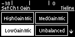
Channel 1 Mic/Line Level Audio Adjustment
The default input level setting in the codec for channel 1 is line level. To adjust this setting for a mic-level or unbalanced source:
1.Press the SETTINGS button.
2.Navigate to Audio and press .
3.Ensure Input Type is set to Analog.
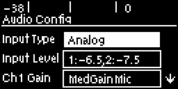
4.Use the arrow-down  button to highlight and select the Ch 1 Gain setting and press the button.
5.Use the navigation buttons to select the appropriate gain setting and press the button to save the setting.
Quick Adjustment of Input Levels
1.Press the  button and the right
  arrow button to open the Input Audio Level screen.
2.Press  on the numeric keypad to toggle channel 1 on and off and press
  to toggle channel 2 on and off.
3.Use the up  and down arrow buttons to navigate to the channel you want to adjust. Note: A channel is highlighted when selected.
4.Use the left  and right arrow buttons to adjust the input levels up or down.
5.Press the RETURN  button to exit the screen.
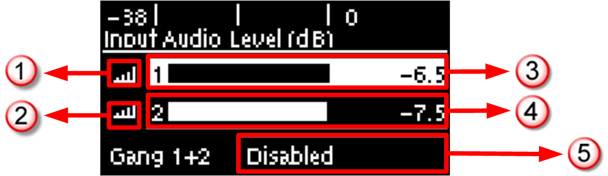
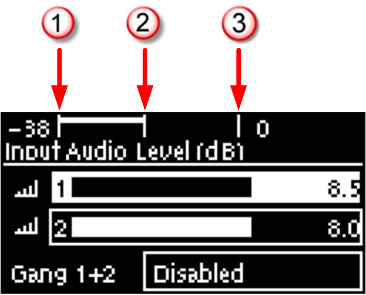
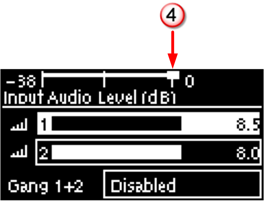
|
Input Audio Features |
Description |
1 |
Channel On Symbol |
Symbol indicates a channel is turned on |
2 |
Channel Off Symbol |
Symbol indicates a channel is turned off |
3 |
Input 1 Level Control |
Input 1 gain indication; adjust in 0.5db increments |
4 |
Input 2 Level Control |
Input 2 gain indication; adjust in 0.5db increments |
5 |
Ch1/2 Gang Indication |
Indicates whether ganging is enabled or disabled |
Intelligent Gain Control (IGC)
When the broadcast action really starts to heat up, the codec's inbuilt DSP limiter automatically takes care of any instantaneous audio peaks that occur in demanding broadcast situations. IGC (Intelligent Gain Control) is enabled by default and is activated at +20 dBu (G5 audio scale) and +14dBu (G3 audio scale) to prevent audio clipping. IGC automatically adjusts high audio input levels downwards until they are acceptable. If IGC auto level recovery (IGC Level) is not enabled, the input level will remain at the adjusted point until the input gain is manually adjusted again by the user. If IGC is active in the codec it is indicated in the PPM meter section. To adjust this setting:
1.Press the SETTINGS button.
2.Navigate to Audio and press .
3.Navigate to IGC and press to toggle between Enabled and Disabled.
IGC Auto Level Recovery
IGC Level works with IGC to detect when incoming audio levels have reduced sufficiently. There are two settings; Auto and Fixed.
If the IGC Level setting is Auto then the codec will return input levels to the gain setting prior to IGC being activated. The codec takes just 250 milliseconds to detect audio levels have returned to normal (after IGC Level has been initiated) and will then return the levels to the previous setting within half a second. This response is linear.
If the setting is Fixed then audio levels will remain lower and not return to the original setting. To adjust this setting:
1.Press the SETTINGS button.
2.Navigate to Audio and press .
3.Navigate to IGC Level and press to toggle between Auto and Fixed.
Ganging Audio Channels
Ganging allows you to adjust the audio level of both inputs simultaneously.
1.Press the button and the right arrow button to open the Input Audio Level adjustment screen.
2.Use the up and down arrow buttons to navigate to and select Gang 1 + 2 Enabled or Disabled.
3.Press the button to select Enabled.
4.Use the up and down arrow buttons to highlight and select the audio channels.
5.Use the left and right arrow buttons to adjust the levels for both inputs up or down simultaneously.
6.Press the RETURN button to exit the screen.
When channels 1 and 2 are ganged together:
•Both channels highlight together when selected.
•You can adjust the audio of both channels simultaneously.
•The gain setting for both channels is automatically set to match the gain level of the lowest of the two channels when ganging is configured.
•If one channel is turned on when ganging is configured then the other is turned on automatically.
