Product |
Feature |
Notification |
Gateway 4 |
Sources and Destinations |
Configure up to 4 mono, or 2 stereo, or 1 x 8 channel (with up to 4 active channels) Source/Destination streams. |
Gateway 8/16 |
Sources and Destinations |
Configure up to 16 mono, or 8 stereo, or 2 x 8 channel AES67 Source/Destination streams in a Gateway 16; configure up to 8 mono, or 4 stereo, or 1 x 8 channel Source/Destination stream in the Gateway 8 codec. |
More information about individual settings in this section are available in the AES67 Setup section within this manual.
Creating an AES67 Source (Outgoing audio stream from Tieline codec)
1.To create an outgoing Source stream open the Tieline AoIP Web-GUI. Note: if you don't know the IP address of the codec on the AES67 LAN, open Toolbox HTML5 Web-GUI for the codec and then open the AoIP Host Network panel in the AoIP menu to view the address.
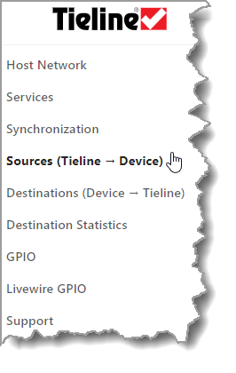
2.In the AoIP Web-GUI select Sources (or in the HTML5 Toolbox Web-GUI click AoIP and then Sources to open the Sources panel).
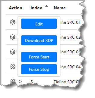
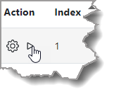
3.Choose a stream to configure and select the Configuration symbol  , then click Edit. Note: Matrix Editor hard coded Source output channel assignments for streams depend on the stream configuration mode. This is outlined in the table that follows later in this section.
4.Edit the Name of the stream if required. Note: this is for identification purposes only and has no effect on the stream.
5.The multicast Address is entered into the AoIP device that will receive a client multicast stream and the UDP Port should also be configured correctly. Note: use the default destination address or edit as appropriate. Take care to not use one of the reserved addresses (see https://en.wikipedia.org/wiki/Multicast_address).
6.Select the preferred primary AoIP Interface used to stream audio.
7.Select the Frame Size (packet time) from 125 microseconds to 4 milliseconds.
8.Configure the Codec Type. In most situations this will be L24 (24 bit).
9.Streams 1 and 9 can be configured in either 2 Channel or 8 Channel Mode. This mode needs to be configured in both devices for streaming to succeed. Streams become unavailable when 8 Channel mode is selected, based on how many channels out of 8 are selected. Note: The number of channels available depends on the model of codec purchased and channel licenses installed.
10.Configure the Type of connection. For most connections this will be mono or stereo; streams 1 and 9 can also be configured to stream between 1 and 8 channels of audio. Up to 8 PPMs are displayed for a single stream with up to 8 channels of audio.
11.Click Save to save all configured settings.
12.Verify audio is metering on the PPMs and click the Start symbol  to start streaming. Running appears in green when streams are successfully streaming.

Gateway codec Sources panel
Redundant Streaming
SMPTE ST 2022-7 compliant redundant streaming (Seamless Protection Switching) can be configured for a Source or Destination stream. When configured, the codec transmits two packet streams, one on each interface, containing identical copies of the payload in each packet. This allows hitless merge, whereby a single reconstructed output stream is created through seamless protection switching at the RTP datagram level. For each stream it is possible to select whether port AoIP 1 or AoIP 2 will be used to transmit or receive packets.
|
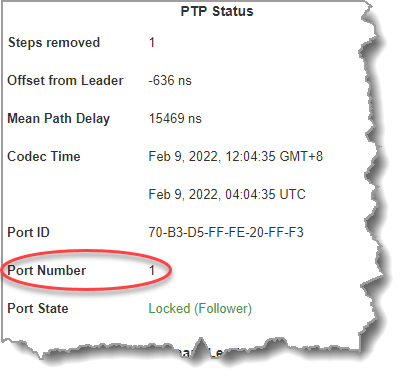
Important Notes: •Two different AoIP interfaces must be configured for redundant streaming. AoIP 1 is the default interface for the primary stream. •While both AoIP ports can be connected to the same switch and use the same subnet, it is recommended that they are connected to separate switches on separate subnets for network resilience. •When a Source employs redundant streaming using the same multicast address then each AoIP interface must be configured with a different subnet. E.g. 192.168.87.x and 192.168.88.x. •If both AoIP ports are on the same subnet then each redundant source stream leg must use a different Destination multicast address. •Multiple PTP Leaders are required to configure redundancy. We recommend using at least two Primary Leader PTP clocks. When configuring PTP in a SMPTE ST2022-7 redundant network setup, each Primary Leader should be connected to both networks in order to avoid different synchronization times in the two networks. E.g. In case only one clock loses its GPS reference signal. PTP Primary Leader synchronization on each interface must have very closely aligned clocks, otherwise glitches may occur when failing over from one Primary Leader to the other. For example, in the case of a link failure, if a PTP Leader fails over to a redundant PTP Leader clock, PTP sync will be lost momentarily until it locks to the redundant Leader clock. The AoIP Port Number change will be displayed in the Synchronization panel.
•DO NOT engage loopback of AES67/ST2022-7 Source and Destination streams on the same codec as this is not supported. |

Configuring Tieline Source Redundant Streaming
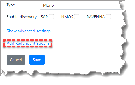
1.In the AoIP Web-GUI select Sources.
2.Select Add Redundant Stream.
3.Insert the multicast address and adjust the redundant streaming Interface if required. Please note: the same multicast address can be used for the primary and redundant streams when each leg is on a different subnet.
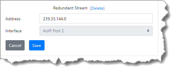
4.Click Save to store the new settings.
Matrix Editor Source Output Assignments
When streaming in AES67 mode, the Matrix Editor hard coded output channel assignments depend on the stream configuration Mode. Verify audio is displayed on the PPMs in the Sources panel before commencing streaming.
AoIP Audio Stream |
Mode |
Mix Outputs Used |
Source 1 |
Mono |
1 |
Stereo |
1 and 2 |
|
8 Channel |
1 to 8 |
|
Source 2 |
Mono |
2 |
Source 3 |
Mono |
3 |
Stereo |
3 and 4 |
|
Source 4 |
Mono |
4 |
Source 5 |
Mono |
5 |
Stereo |
5 and 6 |
|
Source 6 |
Mono |
6 |
Source 7 |
Mono |
7 |
Stereo |
7 and 8 |
|
Source 8 |
Mono |
8 |
Source 9 |
Mono |
9 |
Stereo |
9 and 10 |
|
8 Channel |
9-16 |
|
Source 10 |
Mono |
10 |
Source 11 |
Mono |
11 |
Stereo |
11 and 12 |
|
Source 12 |
Mono |
12 |
Source 13 |
Mono |
13 |
Stereo |
13 and 14 |
|
Source 14 |
Mono |
14 |
Source 15 |
Mono |
15 |
Stereo |
15 and 16 |
|
Source 16 |
Mono |
16 |
Source SDP File Download
SDP is a format for describing RTP sessions and operating parameters, including network addressing, encoding format and other metadata. When configuring Destination streams on other devices, it is possible to download an SDP file for each Tieline codec AES67 audio stream and copy the text file contents into other devices to configure the stream on that device. To copy Tieline codec Source stream information onto other devices supporting this feature:
1.Choose a stream to configure and select the Configuration symbol , then click Download SDP.
2.Save the file on a computer and using a text file editor copy the text from within the file and paste it into the Destination stream on the other device supporting this feature. Note: not all devices support this feature.
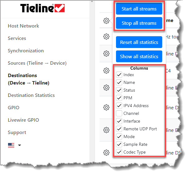
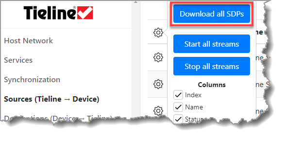
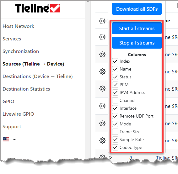
Download all Source SDP Files and Select Columns to Display
To download all Source SDP files simultaneously select the Configuration symbol at the top of the screen and click Download all SDPs. Note: It may be necessary to "allow" the download of multiple files in your browser.
|
Helpful Tip: Select the Configuration symbol
|

|
Important Notes: •Two different AoIP interfaces must be configured for redundant streaming. AoIP 1 is the default interface for the primary stream. •While both AoIP ports can be connected to the same switch and use the same subnet, it is recommended that they are connected to separate switches on separate subnets for network resilience. •When a Source employs redundant streaming using the same multicast address then each AoIP interface must be configured with a different subnet. E.g. 192.168.87.x and 192.168.88.x. •If both AoIP ports are on the same subnet then each redundant source stream leg must use a different Destination multicast address. •Multiple PTP Leaders are required to configure redundancy. We recommend using at least two Primary Leader PTP clocks. When configuring PTP in a SMPTE ST2022-7 redundant network setup, each Primary Leader should be connected to both networks in order to avoid different synchronization times in the two networks. E.g. In case only one clock loses its GPS reference signal. PTP Primary Leader synchronization on each interface must have very closely aligned clocks, otherwise glitches may occur when failing over from one Primary Leader to the other. For example, in the case of a link failure, if a PTP Leader fails over to a redundant PTP Leader clock, PTP sync will be lost momentarily until it locks to the redundant Leader clock. The AoIP Port Number change will be displayed in the Synchronization panel.
•DO NOT engage loopback of AES67/ST2022-7 Source and Destination streams on the same codec as this is not supported. |
Creating an AES67 Destination (Incoming audio stream to Tieline codec)
1.To create an incoming Destination stream it is necessary to find out the multicast address and port used by the device sending the stream to the codec over the AES67 LAN.

Example of LAWO device displaying its Multicast Source IP address and port
2.This information can be used to create a Destination audio stream in the codec as follows. Note: Matrix Editor input channel assignments for Destination streams depend on the stream configuration Mode. This is outlined in the table that follows later in this section.
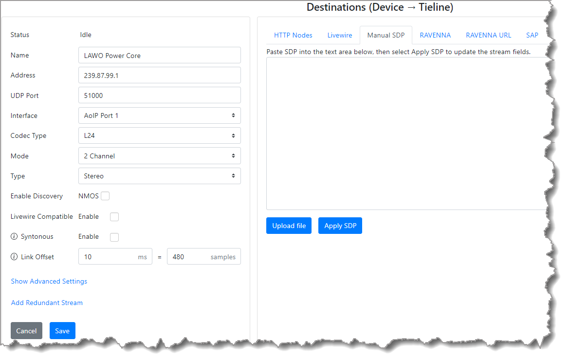
3.Click Save to save all configured settings.
4.Click the Start symbol to commence streaming. Running appears in green when successfully streaming and incoming audio should appear on the PPMs.
Configuring Destination Redundant Streaming
SMPTE ST 2022-7 compliant redundant streaming can be configured for an incoming destination stream.
1.In the AoIP Web-GUI select Destinations.
2.Select Add Redundant Stream.
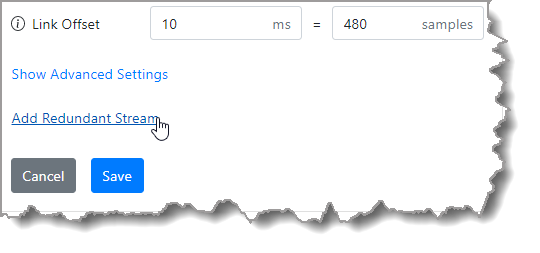
5.Insert the multicast address and adjust the redundant streaming Interface if required. Please note: the same multicast address can be used for the primary and redundant streams.
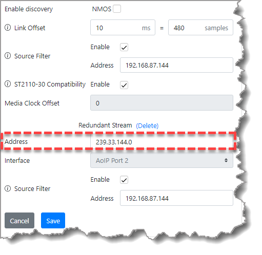
6.Click Save to store the new settings.
|
Important Note: •The destination Link Offset for redundant streams must be configured for the leg which has the highest link latency/jitter. •The Link Offset includes link delay and receiver jitter buffer delay. To calculate the Link Offset setting determine network delay, including time in transmitter jitter buffers, and then add receiver jitter buffer latency. Ensure the Link Offset is higher than the total of network and jitter latencies. |
Matrix Editor Destination Input Assignments
When streaming in AES67 mode, the Matrix Editor input channel assignments depend on the stream configuration Mode as displayed in the following table.
AoIP Audio Stream |
Mode |
Mix Inputs Used |
Destination 1 |
Mono |
1 |
Stereo |
1 and 2 |
|
8 Channel |
1 to 8 |
|
Destination 2 |
Mono |
2 |
Destination 3 |
Mono |
3 |
Stereo |
3 and 4 |
|
Destination 4 |
Mono |
4 |
Destination 5 |
Mono |
5 |
Stereo |
5 and 6 |
|
Destination 6 |
Mono |
6 |
Destination 7 |
Mono |
7 |
Stereo |
7 and 8 |
|
Destination 8 |
Mono |
8 |
Destination 9 |
Mono |
9 |
Stereo |
9 and 10 |
|
8 Channel |
9-16 |
|
Destination 10 |
Mono |
10 |
Destination 11 |
Mono |
11 |
Stereo |
11 and 12 |
|
Destination 12 |
Mono |
12 |
Destination 13 |
Mono |
13 |
Stereo |
13 and 14 |
|
Destination 14 |
Mono |
14 |
Destination 15 |
Mono |
15 |
Stereo |
15 and 16 |
|
Destination 16 |
Mono |
16 |
SDP Destination File Upload, or SDP Copy and Paste Function
When configuring Destination streams on a Tieline codec it is possible to upload an SDP file, or copy and paste the contents of an SDP text file, for each audio stream configured. To facilitate this feature, the other device must support SDP text file creation, or copying and pasting SDP info. Note: WheatNet-IP Blades and Telos xNodes support this feature.
|
Important Note: Ensure a stream is not running when uploading an SDP file or pasting SDP data into the web-GUI or it will fail. |
To upload a saved SDP text file with Destination information:
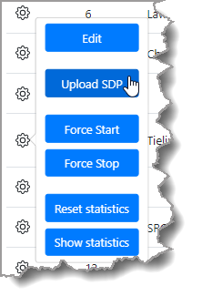
1.Select the Configuration symbol on a stream and then click Upload SDP.
2. Select a saved SDP file and upload it.
To copy and paste SDP information from a text file into a Destination:
1.Select the Configuration symbol on a stream and then click Edit.
2.Copy the SDP information from the text file extracted from the other device into the text box adjacent to the Apply SDP button.
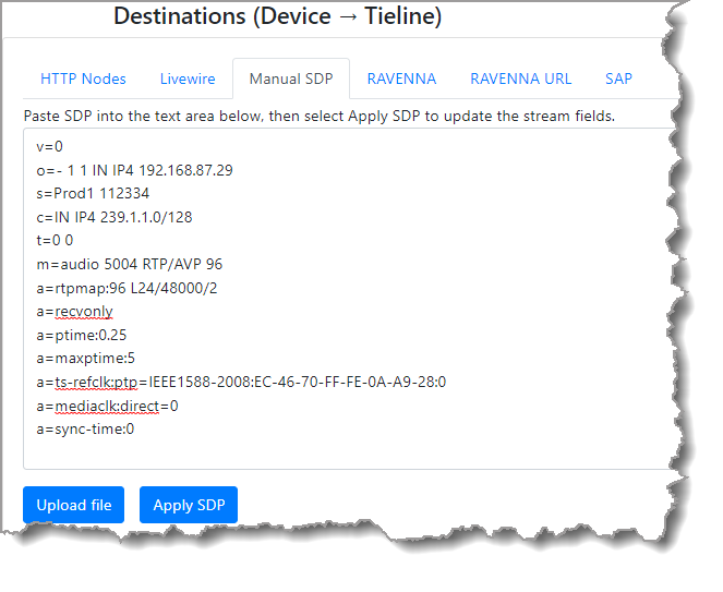
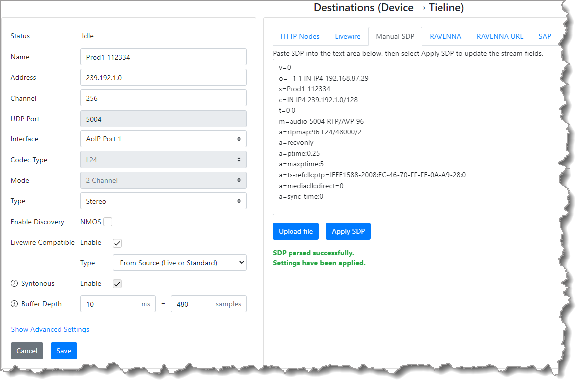
3.Click the Apply SDP button.
4.Ensure Destination settings have been populated correctly and click Save.
|
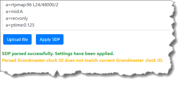
Important Note: If there is a PTP mismatch, a warning will display in the Destinations panel stating Parsed Grandmaster clock ID does not match current Grandmaster clock ID. This may occur when there is a change in a PTP Primary Leader and an SDP file has been generated using info from a previous PTP clock.
To avoid this message, download a new Source SDP file and apply this SDP file in the Destinations panel. |
5.Click the Start symbol to commence streaming. Running appears in green when streams are successfully streaming.
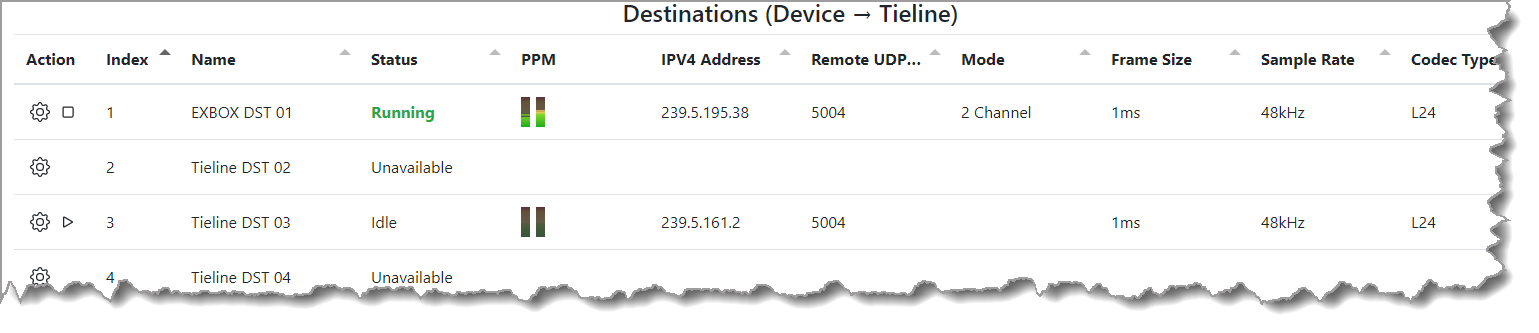
Source and Destination Status Indications
Following are the Status indications for a Source and Destination.
Source Status Displayed |
Source Status Description |
Idle |
The stream is configured and not running |
Running |
The stream is active and running |
Unavailable |
The stream is unavailable because it is allocated to another stream |
Unlicensed |
The stream requires a license upgrade to be available for streaming |
Error |
The stream has detected an error. This will also appear when an IP interface is removed. Stop and restart a stream to remove this error message. |
Destination Statistics
There are two ways to monitor Destination packet and jitter statistics.
Statistics in Destinations Panel
1.Select the Configuration symbol for a Destination, click Edit, and then Show statistics.
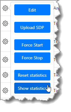
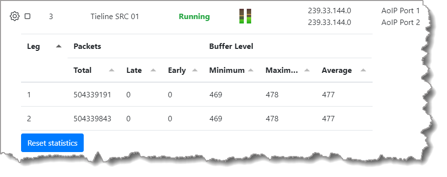
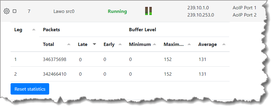
Packet and jitter stats are displayed for each Destination Interface.
|
Important Note: •If the Minimum displays 0 this indicates the buffer has emptied and it is recommended that the Link Offset be increased to avoid artifacts and loss of audio.
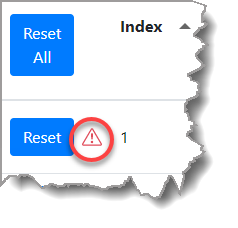
•A red Caution symbol is displayed when a Destination stream issue may require attention. Examples of when this will appear include: oLate packets: If packets have been received late and have been lost the Link Offset may need to be increased. If the Minimum for received packets is a number close to zero (or zero) the Link Offset should be increased. oEarly packets: If packets arrive early and the buffer is already full packets will be dropped. Decreasing the Link Offset may resolve this issue. Also check that the sender and receiver are properly synchronized to the same PTP Primary Leader. oZero Minimum Buffer Level: A warning is displayed if the stream is running and the buffer has previously emptied. oHigh Maximum Buffer Level: If the Maximum latency is high, e.g. over 1000, causes of high network latency should be investigated.
|
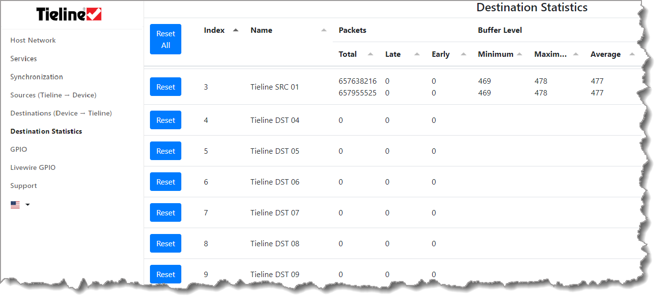
Destination Statistics Panel
1.In the AoIP Web-GUI select Destination Statistics.
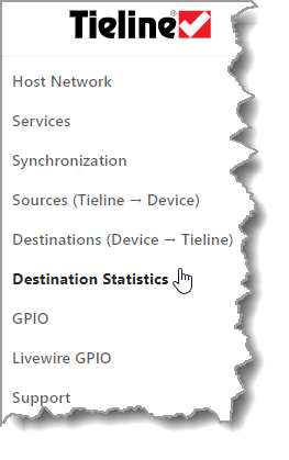
2.This provides an overview of packet and jitter statistics for all Destinations in one screen.
Reset Statistics
Click the Reset button to reset the statistics for a Destination or click Reset All to reset the statistics for all streams in the Destinations Statistics panel. It is also possible to show, hide, and reset Destination statistics from within the Destinations panel.
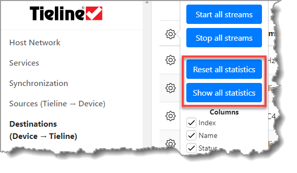
1.In the AoIP Web-GUI select Destinations.
2.Select the Configuration symbol at the top of the screen and click to show and hide statistics for all Destination streams within the panel; click Reset all statistics to reset the display.
|
Helpful Tip: Select the Configuration symbol
|