How to Configure AoIP Settings in Tieline Codecs
There are two ways to configure AoIP Sources and Destinations: Tieline's HTML5 Toolbox Web-GUI, or the AoIP Web-GUI.
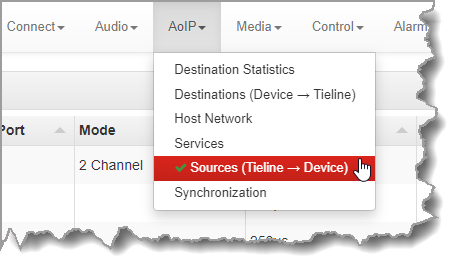
1.Tieline's browser-based AoIP Web-GUI configuration tool configures codec AoIP streams when a computer is connected to an AES67 LAN. The AoIP Web-GUI has a several screens that allow:
•Configuration of source and destination audio streams.
•Monitoring and configuration of Synchronization settings.
•Monitoring and configuration of Host Network settings.
•Viewing Destination Statistics.
•GPIO monitoring and configuration.
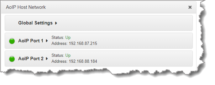
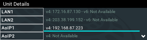
To access the AoIP Web-GUI type the IP address of the AoIP port interface into a browser, or type the codec hostname using the following format: http://TLR6200-61086-AOIP. Hostname and IP address details can be found in the codec via the AoIP Host Network panel accessed via the HTML5 Toolbox Web-GUI AoIP menu. Alternatively, from the codec Home screen select Settings > Unit Details > AoIP1/2 to view the AoIP network IP address.
The AoIP Web-GUI looks a bit different to the HTML5 Toolbox Web-GUI but the functionality in the available AoIP panels is the same.

Gateway-16 AoIP Web-GUI for Configuring Sources and Destinations
2.The easiest way to configure settings remotely when away from the studio is with the Toolbox HTML5 Web-GUI connected to a codec via a WAN/LAN connection. All AoIP settings can be configured in the panels available within the AoIP menu at the top of the Web-GUI screen. The Audio Options panel can also be used to configure digital I/O settings, like selecting AES3 or AoIP as codec inputs or outputs. The Cloud Codec Controller can also be used to configure and monitor connections and audio streams.
|
Important Note: The AoIP Web-GUI displays all the panel settings available within the AoIP menu in the Toolbox HTML5 Web-GUI. |

Configure AoIP Host Network Settings
To discover the IP address of an AES67 host network using the codec front panel:
1.Press the SETTINGS  button.
2.Use the navigation buttons to select Unit Details and press the  button.
3.IP address details are displayed under the LAN address details and the address can be used to launch the AoIP Web-GUI.
It's simple to configure host network settings using the AoIP Host Network panel which is accessed from the HTML5 Toolbox Web-GUI AoIP menu.
1.Click Edit to adjust the Hostname or IP Mode and IP address details etc.
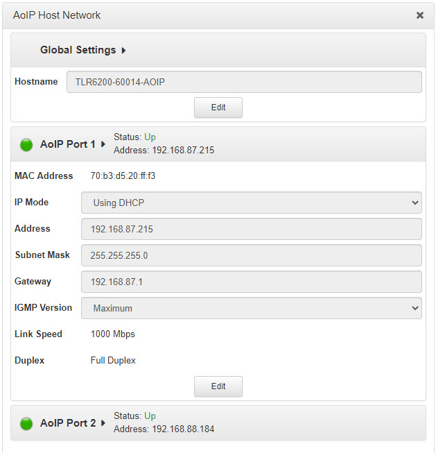
2.Click Save to store new settings.
Configuring Codec Inputs and Outputs for AoIP Streaming
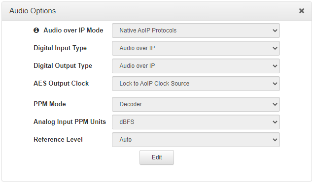
Some global AoIP-related settings reside in the Audio Options panel in the HTML5 Toolbox web-GUI. These include:
1.Audio over IP Mode (Note: this setting is only visible if a codec has WheatNet-IP card or Dante card (future release) installed):
•Native AoIP Protocols (AES67, ST2110-30, Livewire+, RAVENNA), or
•WheatNet-IP, or.
•Dante.
2.Digital Input Type: AES3 or Audio over IP (AES67, ST 2110-30, Livewire+, RAVENNA, WheatNet-IP and Dante).
3.Digital Output Type: AES3 or Audio over IP (AES67, ST 2110-30, Livewire+, RAVENNA, WheatNet-IP and Dante).
To adjust these settings:
1.Open the HTML5 Toolbox Web-GUI and click Audio at the top of the screen, then click Audio Options to display the Audio Options panel.
2.Click Edit to adjust settings.
3.Click Save to save settings.
|
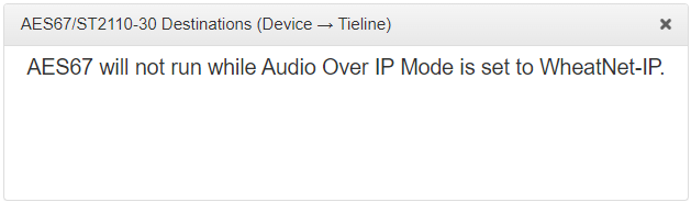
Important Note: When the codec is configured for WheatNet-IP the Tieline AoIP Web-GUI in the codec is inactive because the device AoIP interface is controlled by Wheatstone's Navigator software.
|
Audio over IP Mode
If an optional WheatNet-IP card is installed in the codec select WheatNet-IP as the AoIP mode for used by the codec. This mode supports connecting to WheatNet-IP LANs and allows codec stream configuration using Navigator software. Select Native AoIP Protocols as the AoIP mode when connecting with natively supported AES67, ST2110-30, Livewire+ and RAVENNA protocols.
Digital Input Type
Select either AES3 or Audio over IP as the Digital Input Type for the codec. This setting is global for all digital inputs.
|
Important Note: PPMs on the AoIP Destinations panel are inactive if the Digital Input Type is not set to Audio over IP and the corresponding input Type is not set as Digital. |
Digital Output Type
Select either AES3 or Audio over IP as the Digital Output Type for the codec. This setting is global for all digital outputs.
Sources and Destinations
Sources and destinations identify outgoing and incoming AoIP streams and are configured separately. When configuring streams, a codec 'source' is an endpoint from which a stream is sent by the codec to an AoIP network, and a 'destination' is an endpoint at which a stream is received from an AoIP network by the codec.
One way to remember this is to think of the codec as an 'edge' device, bridging the divide between WANs like the internet, and a studio AoIP network. Most devices are configured with a studio-centric approach, so streams sent to the codec from the studio AoIP network, e.g. a WheatNet AoIP network, route audio to codec destinations. Therefore the codec receives audio as a 'destination' from the studio's perspective. Accordingly, the studio receives audio from the codec as an AoIP network 'source'.
Product |
Feature |
Notification |
Gateway 4 |
Sources and Destinations |
Configure up to 4 mono, or 2 stereo, or 1 x 8 channel (with up to 4 active channels) Source/Destination stream in the Gateway 8 codec. |
Gateway 8/16 |
Sources and Destinations |
Configure up to 16 mono, or 8 stereo, or 2 x 8 channel AES67 Source/Destination streams in a Gateway 16; configure up to 8 mono, or 4 stereo, or 1 x 8 channel Source/Destination stream in the Gateway 8 codec. |
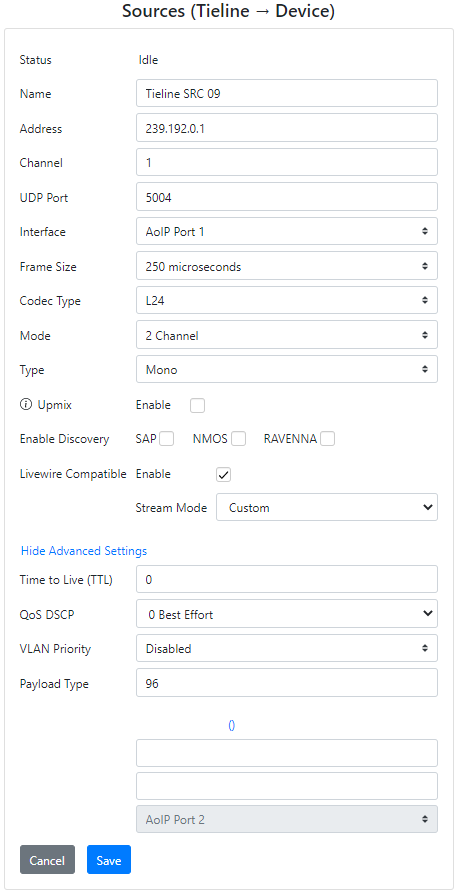
Source Configuration Settings
Configurable Source settings for audio streams sent by the Tieline codec over the AES67 LAN are listed in the following table.
Parameter |
Settings |
Name |
Source stream name for identification purposes only; no effect on stream. |
Address |
Multicast IP address details; the default address for 16 source streams is 239.33.1.0 to 239.33.1.15. |
UDP Port |
The default UDP streaming port for RTP packets is usually 5004 |
Interface |
Select the primary AoIP interface to use for the source stream. |
Frame Size |
Various settings from 125 microseconds to 4 milliseconds |
Codec Type |
Choose from L16 (16 bit) or L24 (24 bit) sampling; note the sampling frequency is configured in the Synchronization panel and is usually 48 kHz. All streams us a common sampling rate. |
Mode |
Select from 2 channel or 8 channel streaming in streams 1 and 9; this setting is not available for other streams and 2 channel is the default. Note: streams become unavailable when 8 Channel mode is selected, based on how many channels out of 8 are selected. Note: The number of channels available depends on the model of codec purchased and channel licenses installed. Between 8 and 16 channels may be available. |
Type |
Configure mono or stereo streams; 3 - 8 channels also available for streams 1 and 9. |
Upmix |
Select the Enable check-box to duplicate a mono channel for a stereo stream. |
Enable Discovery |
Select a discovery protocol for simplified stream connection management, e.g. SAP, NMOS and/or RAVENNA. Note: No SAP announcements are sent if PTP is not locked. |
Livewire Compatible |
Select the Enable check-box to fix several parameters to values compatible with Livewire Sources. |
Stream Mode |
Select the preferred Livewire+ Stream Mode to suit the type of Source being configured. |
Time To Live (TTL) |
Setting used in multicast routers to ensure data packets have a finite life and don't cause congestion over networks. Each time a packet passes through a router it reduces by 1 until it reaches zero, at which point a router will no longer pass the packet. |
QoS DSCP |
Quality of Service setting using the DiffServ method as described in RFC 2474. Uses the DSCP field to mark packets according to their packet class. 34 is the default setting and recommended for AES67. 46 is used for expedited forwarding. |
VLAN Priority |
Represents a QoS prioritization scheme for Ethernet frames. |
Payload Type |
Some equipment requires a payload setting and the Tieline default setting is 96 |
Add Redundant Stream |
Add a redundant IP stream and transmit an identical IP packet stream over a different AoIP interface. Packets are seamlessly reconstructed by the receiver to ensure flawless audio is received. |
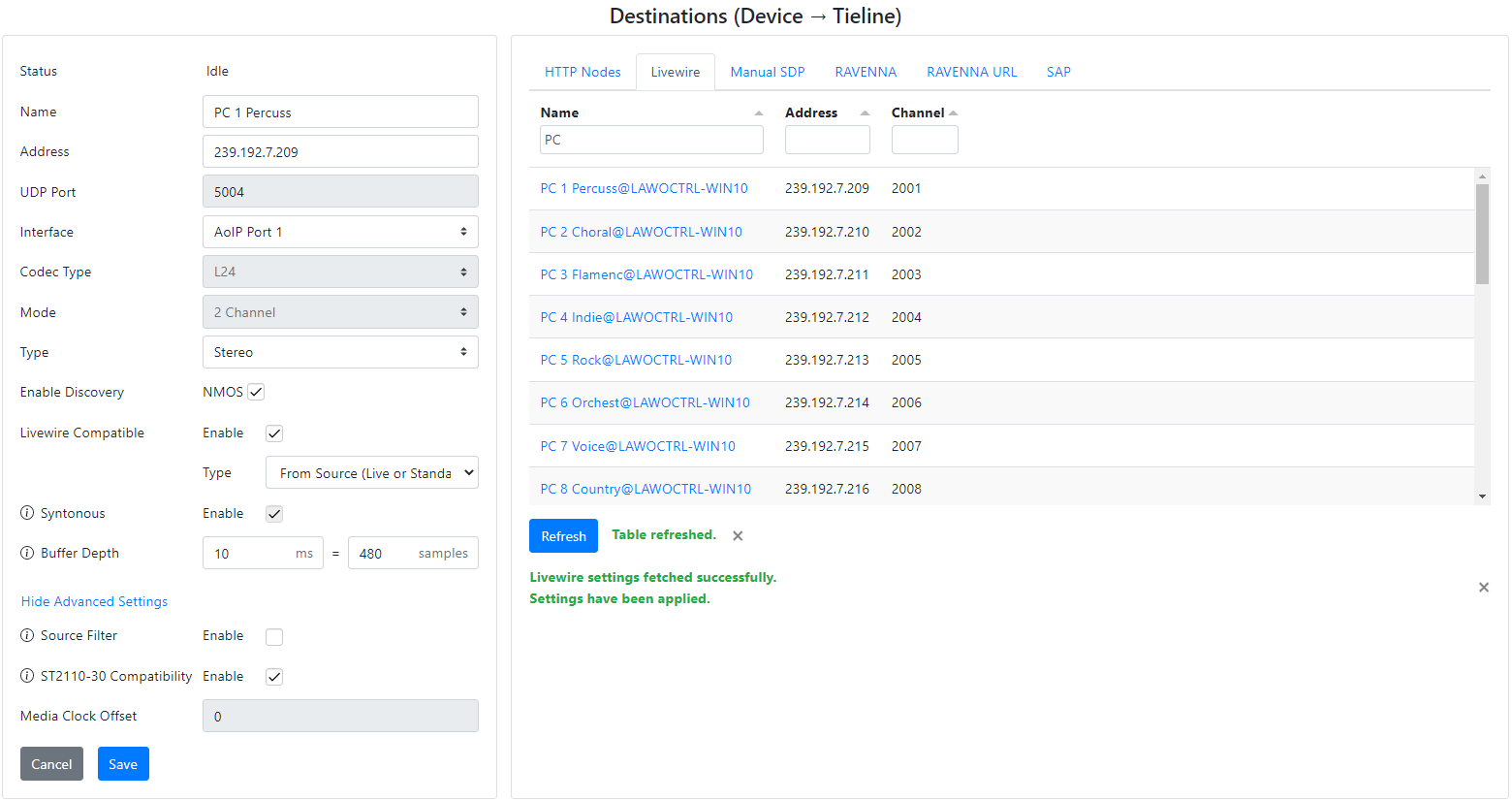
Destination Configuration Settings
Configurable Destination settings for audio streams received by the codec over the AES67 LAN are listed in the following table.
Parameter |
Settings |
Name |
Destination stream name |
Address |
Multicast IP address details; the default address for 16 destination streams is 239.46.1.0 to 239.46.1.15. Note: The default destination multicast address will normally be configured by the device streaming audio to the Tieline codec. Verify this address with the network IT administrator and then place the correct address into the Address text box in the Destinations panel. |
Channel |
The unique channel number used by Livewire to identify streams. Note: Only displayed for Livewire streams. |
UDP Port |
The default UDP streaming port for RTP packets is usually 5004 |
Interface |
Select the primary AoIP interface to use for the destination stream. |
Codec Type |
Choose either L16 (16 bit) or L24 (24 bit) samples. All streams us a common sampling rate. |
Mode |
Select from 2 channel or 8 channel streaming in streams 1 and 9; this setting is not available for other streams and 2 channel is the default. Note: streams become unavailable when 8 Channel mode is selected, based on how many channels out of 8 are selected. |
Type |
Configure mono or stereo streams; 3 to 8 channels also available for streams 1 and 9. |
Downmix |
•Applies -6dB of gain reduction to left and right channels of the received 2 channel stereo stream and downmixes into mono. Note: When configuring a mono Destination stream, if a stereo RAVENNA, SAP or Livewire stream is parsed, then Downmix will be automatically selected for compatibility. RAVENNA and SAP include SDP info on the number of channels in a stream. |
Enable Discovery |
Select the check-box to enable NMOS discovery and configuration/control of a Destination audio stream. |
Livewire Compatible |
Select the check-box to Enable Livewire+ compatibility in the codec. This feature fixes some parameters to values compatible with Livewire Destinations. The Livewire tab in the Destinations panel displays all advertised Livewire+ Sources across the network. |
Type |
The Livewire Compatible stream Type is typically configured when a Livewire stream is parsed using the Livewire tab. It can also be manually configured using the Type drop-down menu. Options define elements like whether a specific Livewire IP address range is configured, or a custom stream configuration can also be defined. |
Syntonous |
Syntonous receive mode is used by default in Livewire Destinations and is supported by some other vendors. In Syntonous mode the sampling frequency is locked, but the absolute time reference at the sender and receiver may be different. Redundant streaming is not supported in this mode. |
Buffer Depth |
The storage buffer used to capture incoming data packets when operating in Syntonous mode. It ensures the continuity of audio streams by smoothing out packet arrival times during periods of network congestion. |
Link Offset |
The Link Offset is defined as the difference in time between when the audio enters the transmitter and exits the receiver. The link delay setting must be greater than the worst case link delay, taking into account network jitter. This setting is not available in Syntonous mode. |
Source Filter Enable (Advanced Settings) |
Select the check-box to enable and disable Source filtering. |
Source Filter Address (Advanced Settings) |
Only accept data from the origin address that is pushing to the multicast address. Leave empty to accept any source address. |
ST 2110-30 Compatibility |
Select the Enable check-box to configure the Media Clock Offset setting as 0. This is required for ST2110-30 compliant streaming. |
Media Clock Offset |
Configurable Media Clock Offset setting. Note: when ST 2110-30 Compatibility is enabled this setting is greyed out and set to 0. |
Add Redundant Stream |
Add a redundant IP stream and stream an identical IP packet stream over a different AoIP interface. Packets are seamlessly reconstructed by the receiver to ensure flawless audio is received. |
HTTP Nodes |
RAVENNA allows advertisement of web management interfaces controlling devices to which you are connecting. The HTTP Nodes tab displays Hostname and Address links to launch a device management interface directly. |
Livewire |
Displays available Livewire+ Sources. When a Source is selected, the SDP is fetched, parsed and populated in the fields within the Destinations panel. |
Manual SDP |
Copy and paste SDP text from an AES67 compatible device and click the Parse SDP button to configure a destination stream. This will configure the codec to receive an audio stream from a device. |
RAVENNA tab |
Displays available RAVENNA Sources. When a Source is selected, the SDP is fetched, parsed and populated in the fields within the Destinations panel. |
RAVENNA URL tab |
Copy a known RTSP URL address for a device and then paste into the RAVENNA URL tab to populate data in the Destinations panel. |
SAP tab |
Displays sources advertised using SAP. When a Source is selected, the SDP is fetched (and can be viewed), then it can be parsed and populated in the fields within the Destinations panel. |
Use the following sections to configure Source and Destination streams for the various proprietary AoIP systems.