Product |
Feature |
Notification |
Gateway 4 |
Analog / AES3 Inputs / Outputs (4 Analog / AES3 in/out) |
ANALOG/AES3 IN RJ-45 connectors provide shared stereo analog line inputs 1-4, or stereo AES3 digital inputs 1-4. ANALOG/AES3 OUT RJ-45 connectors provide shared stereo analog line outputs 1-4, or stereo AES3 digital outputs 1-4. |
Gateway 8/16 |
Analog / AES3 Inputs / Outputs (8 Analog in/out; 16 AES3 in/out) |
ANALOG/AES3 IN RJ-45 connectors provide shared stereo analog line inputs 1-4, or stereo AES3 digital inputs 1-4. Connectors 5-8 provide stereo AES3 digital inputs 5-8. Balanced ANALOG/AES3 OUT RJ-45 connectors provide shared stereo analog line outputs 1-4, or stereo AES3 digital outputs 1-4, plus stereo AES3 digital outputs 5-8. |
Codecs feature stereo AES inputs and outputs on the rear panel of the codec for AES3 (AES/EBU) format audio. These balanced 110 ohm inputs can operate effectively over distances of up to 100 meters and accept both mono and stereo AES3 signals.
Configuring AES3 Inputs and Outputs Globally
Either analog or digital audio is supported via RJ-45 inputs. To configure codec inputs and outputs for digital AES3 requires two settings to be configured for inputs and outputs 1-4 (Gateway 4) and inputs and outputs 1-8 (Gateway 8/16). First, the codec needs to be configured globally for AES3 input and output audio, instead of digital AoIP audio. Next, ensure inputs are configured for AES3 digital audio via Settings > Audio Inputs > Type.
1.Press the SETTINGS  button.
2.Navigate to Audio Options and press the  button.
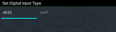
3.Select Dig. Input Type or Dig. Output Type and press the button.
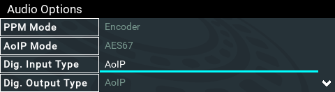
4.Select AES3 and press the button.
Note: Gateway 16 codec inputs and outputs 9-16 are configured for AES3 when the Dig. Input Type and Dig. Output Type are set for AES3 audio.
Configuring Inputs for Digital or Analog Audio
Inputs and outputs 1-4 (Gateway 4) and inputs and outputs 1-8 (Gateway 8/16) can be configured in pairs for either Analog or Digital audio. After selecting AES3 globally for inputs and outputs in the Dig. Input Type or Dig. Output Type menu, next ensure inputs and outputs are configured at the input/output level:
1.Press the SETTINGS button.
2.Navigate to Audio Inputs or Audio Outputs and press the button.
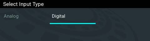
3.Navigate to Type and press the button.
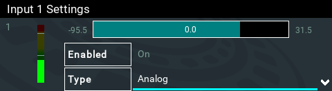
4.Select Digital and press the button.
|
Important Notes: •There is a maximum of 6dB of additional gain available when adjusting an AES3 digital input. •If you switch back to the analog input setting after selecting AES3, the previous analog settings will be recovered. |

AES3 Out Clock Source
The codec contains two sample rate converters.
Input Sample Rate Converter
The codec implements an Asynchronous Sample Rate Converter (ASRC) to convert the sample rate of an AES3 input to the sample rate set in the codec. The codec sample rate is determined by the selected algorithm. For example, if you select the Music algorithm, the sample rate will be set to 32kHz. By default the codec will up-sample all AES3 input sources to 96kHz sampling and then convert to match the AES output sample rate setting.
|
Important Note: All AES3 inputs must have the same sample-rates and must be synchronized to a common clock. See Appendix B for pin-outs of AES3 inputs. |
Output Sample Rate Converter
The sample rate of the AES3 output is configured using the clock source setting via the SETTINGS button and then Audio Options > AES3 Out Clock Src. This configures the sample rate frequency of all AES3 output signals.
Wordclock Sync In
This setting configures the codec for a word clock source via the SYNC I/O 2 BNC connector on the codec rear panel (this is the same as the External Word Clock setting in Tieline G3 codecs). Often this will be a studio reference signal. In television broadcasting facilities the audio reference signal should be locked to the video reference if there is one available. The sample rate being received is recognized by the codec and automatically adjusted. Supported sample rates include 32 kHz, 44.1 kHz, 48 kHz and 96 kHz. Note: The reference clock must be within +/- 50ppm of the listed sample rates.
Lock to AES3 Input
With this setting the codec uses AES3 input sync information to set the codec output sample rate (Note: this is the same as the AES Rx Clock setting in Tieline G3 codecs). The codec initially tries to use the signal on AES inputs 1 and 2 as the clock to which the AES outputs are synchronized. If unavailable, it then attempt to use inputs 3 and 4, or inputs 5 and 6 and so on in that order. If you select this option, all AES inputs must always be synchronized to the same clock source, e.g. if AES3 inputs 1 and 2 use 48kHz sampling then all other inputs must also be synchronized to the same clock. Supported sample rates include 32 kHz, 44.1 kHz, 48 kHz and 96 kHz. Note: The reference clock must be within +/- 50ppm of the listed sample rates.
Lock to AES11 Input
AES11 is a standard AES3 signal with an accurate clock reference (DARS, or Digital Audio Reference Signal), usually without the audio data. To use this input attach a female BNC connector to the SYNC I/O 1 connector on the codec rear panel. Supported sample rates include 32 kHz, 44.1 kHz, 48 kHz and 96 kHz. Note: The reference clock must be within +/- 50ppm of the listed sample rates.
Lock to AoIP Clock
AES67/ST2110-30/Livewire derives the sampling clock from a primary leader clock over the network or a Livewire clock. This clock can be selected as the AES3 Output Clock Source. The AES3 Output Clock Source uses the Lock to AoIP Clock setting if either the Digital Input Type or Digital Output Type is set to AoIP. If a WheatNet-IP card is installed, and the Digital Input Type or Digital Output Type is set to WNIP, then the AES3 Output Clock Source is forced to Lock to WNIP Clock.
Fixed Sample Clock
Select from a range of fixed output sample rates including:
1.32 kHz
2.44.1 kHz
3.48 kHz
4.88.2 kHz
5.96 kHz
Note: The reference clock must be within +/- 50ppm of the listed sample rates.