Product |
Feature |
Notification |
Gateway 4 |
PPM Meters |
8 PPMs on front panel display 4 channel inputs/outputs or encoders/decoders |
Gateway 4 |
Inputs |
4 Channels in/out |
Gateway 4 |
Inputs |
Inputs 1-4 can be configured as analog or digital inputs (AES3 or AoIP) in pairs |
Gateway 8/16 |
PPM Meters |
16 PPMs on front panel can display inputs, or outputs, or encoders, or decoders |
Gateway 8/16 |
Inputs |
8-16 Channels In/Out (depending on configuration purchased) |
Gateway 8/16 |
Inputs |
Inputs 1-8 can be configured as analog or digital inputs (AES3 or AoIP) in pairs |
|
Important Note: See Configuring AES3 audio for more information about digital in/outs. Input audio functions can also be configured using the Toolbox Web-GUI; see Configuring Input/Output Settings for more information. |

Adjusting PPM Meter Reference Scale Settings
By default, the PPM METERS on the front of the codec, or in the HTML5 Toolbox Web-GUI, use dBFS to express nominal operating, headroom and noise floor levels.
The codec can also automatically adapt to different Tieline reference scales. A Tieline codec with proprietary Tieline session data enabled will automatically adjust the reference level to suit G5 and G3 codecs, or Report-IT. When connecting to a non-Tieline codec, or a Tieline codec without session data enabled, the codec will use the Tieline G6 reference scale setting.
The default Tieline G6 audio reference scale displayed on the PPMs when connecting to a Tieline G6 codec is -40dBFS to 0dBFS. Using this reference scale audio peaks can safely reach 0dBFS without clipping, providing 20dB of headroom from the nominal 0vu point. The comparison table below outlines the reference scales for G6, G5, G3 codecs and Report-IT in dBFS, as well as the equivalent dBU scale.

Gateway-16 Codec PPMs Displayed
The audio reference level settings in the codec are:
|
Reference Level |
Description |
dBu |
dBFS |
1 |
Tieline G6 (Gateway, Gateway 4) |
PPM meter low point |
-16dBU |
-40dBFS |
Nominal 0vu reference level |
+4dBU |
-20dBFS |
||
Level at which audio will clip/distort |
+24dBu |
0dBFS |
||
2 |
Tieline G5 (Genie, Merlin, Bridge-IT, ViA) |
PPM meter low point |
-16dBu |
-38dBFS |
Nominal 0vu reference level |
+4dBu |
-18dBFS |
||
Level at which audio will clip/distort |
+22dBu |
0dBFS |
||
3 |
Tieline G3 (Commanderand i-Mix) |
PPM meter low point |
-11dBu |
-29dBFS |
Nominal 0vu reference level |
+4dBu |
-14dBFS |
||
Level at which audio will clip/distort |
+18dBu |
0dBFS |
||
4 |
Report-IT |
PPM meter low point |
-9dBu |
-23dBFS |
Nominal 0vu reference level |
+4dBu |
-10dBFS |
||
Level at which audio will clip/distort |
+14dBu |
0dBFS |
|
Important Note: If a codec supports multiple stream programs and the Auto (default) reference level is selected, the first codec to connect will configure the reference level used for all subsequent connections. I.e. If a G3 codec connects first then the G3 Audio Reference Level will be configured for all connections. |
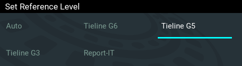
Configure Tieline G5 Audio Reference Scales
Tieline G6 codecs have slightly more headroom than Tieline G5 codecs, therefore the audio metering reference scale needs to be adjusted when G6 codecs connect to G5 Merlin, Genie, ViA and Bridge-IT codecs. The G5 metering scale is between -38dBFS and 0dBFS and audio levels should average around the nominal 0vu point at -18dBFS. Audio peaks should not exceed 0dBFS.
1.Press the SETTINGS  button.
2.Navigate to Audio Options and press the  button.
3.Navigate to Reference Level and press the button.
4.Select Tieline G5 and press the button.
Configure Tieline G3 Audio Reference Scales
Tieline G6 and G5 codecs have more audio headroom than Tieline G3 audio codecs, therefore the audio metering reference scale needs to be adjusted when these codecs connect to a Commander or i-Mix G3 codec. The G3 metering scale is between -29dBFS and 0dBFS and audio levels should average around the nominal 0vu point at -14dBFS. Audio peaks should not exceed 0dBFS.
1.Press the SETTINGS button.
2.Navigate to Audio Options and press the button.
3.Navigate to Reference Level and press the button.
4.Select Tieline G3 and press .
Configure Report-IT Audio Reference Scales
The Report-IT setting is used for compatibility when streaming audio using Tieline's Report-IT smartphone application.
1.Press the SETTINGS button.
2.Navigate to Audio Options and press the button.
3.Navigate to Reference Level and press the button.
4.Select Report-IT and press .
The Report-IT metering scale is between -23dBFS and 0dBFS and audio levels should average around the nominal 0vu point at -10dBFS. Audio peaks should not exceed 0dBFS.
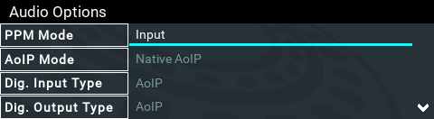
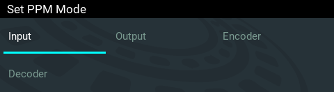
Adjusting PPM Metering
PPM metering options can be adjusted via Settings > Audio Options > PPM Mode. Note: Gateway 4 has 4 inputs, 4 outputs, 4 encoders, 4 decoders, and 8 PPMs only; Gateway 8/16 has 16 PPM meters and between 8 and 16 inputs depending on configuration purchased; encoders and decoders available will match input availability/configuration.
Gateway 8/16
|
PPM Mode |
Gateway 16 Description |
Gateway 8 Description |
1 |
Input (default) |
Maps inputs 1 to 16 with PPM meters 1 to 16 |
Maps inputs 1 to 8 with PPM meters 1 to 8 |
2 |
Output |
Maps outputs 1 to 16 with PPM meters 1 to 16 |
Maps outputs 1 to 8 with PPM meters 1 to 8 |
3 |
Encoder |
Maps input encoders 1 to16 with PPM meters 1 to 16 |
Maps input encoders 1 to 8 with PPM meters 1 to 8 |
4 |
Decoder |
Maps decoders 1 to 16 with PPM meters 1 to 16 |
Maps decoders 1 to 16 with PPM meters 1 to 8 |
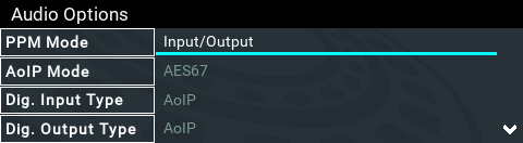
Gateway 4
|
PPM Mode |
Gateway 4 Description |
1 |
Input/Output (default) |
Maps inputs 1 to 4 with PPM meters 1 to 4; maps outputs 1 to 4 with PPM meters 5 to 8 |
2 |
Encoder/Decoder |
Maps input encoders 1 to 4 with PPM meters 1 to 4; maps decoders 5 to 8 with PPM meters 1 to 4 |
Adjusting Input Settings
1.Press the SETTINGS button.
2.Navigate to Audio Inputs and press .
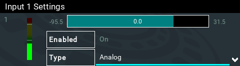
3.Adjustable input settings include:
•Input on/off.
•Input level: ganging of inputs is not currently supported.
•Input Type: Analog (line level input), Digital (AES3 or AoIP).
•IGC.
•Polarity/phase inversion
•Input Name
Selecting Analog or Digital Inputs
1.Press the SETTINGS button.
2.Navigate to Audio Inputs and press .
3.Select an input to adjust and press .
4.Navigate to Type and press .
5.Select Analog or Digital as required. This will configure the associated input as well, e.g. in this example input 2 when input 1 is configured.

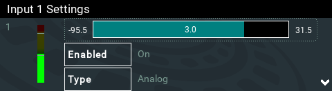
Adjusting Input Levels
1.Press the SETTINGS button.
2.Navigate to Audio Inputs and press .
3.Select an input to adjust and press .
4.Select the level adjustment bar and use the left ![]() and right
and right ![]() navigation buttons to adjust levels up and down. Note: input ganging is not available in the first firmware release.
navigation buttons to adjust levels up and down. Note: input ganging is not available in the first firmware release.
|
Important Note: •Gain adjustments can be made in 0.5dB increments. •There is a maximum of 6dB of additional gain available when adjusting a digital input. •Audio signal processing occurs in the following order: IGC/Limiter (Intelligent Gain Control limiting on the input) > Input Compression > Input EQ > Mixer > Output AGC (Automatic Gain Control limiter). |
Intelligent Gain Control (IGC)
The codec's inbuilt DSP limiter automatically takes care of any instantaneous audio peaks that occur in demanding broadcast situations. Input IGC (Intelligent Gain Control) is enabled by default and is automatically activated at +19 dBu (G6 audio scale), +17 dBu (G5 audio scale) and +13dBu (G3 audio scale) to prevent audio clipping.
There are three settings; Auto, Fixed and Off. If Auto is configured the codec will detect when incoming audio levels have reduced sufficiently and automatically return input levels to the gain setting prior to IGC being activated. The codec takes just 250 milliseconds to detect audio levels have returned to normal (after IGC Level has been initiated) and will return the levels to the previous setting within half a second. This response is linear.
To adjust this setting in the codec:
1.Press the SETTINGS button.
2.Navigate to Audio Inputs and press .
3.Select an input to adjust and press .
4.Navigate to IGC and press .
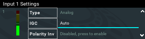
5.Select the preferred setting and press .