Open the HTML5 Toolbox Web-GUI and click Transport and then click Network to view and configure Ethernet and VLAN interface settings in the Web-GUI.
|
Important Note: For assistance with configuration of IPv4 or IPv6 network connections contact your IT Administrator. |

IPv4 versus IPv6
An IP address is a unique address to identify a device on a TCP/IP network. Your codec uses dual IP protocol stacks to allow your codec to work on both IPv4 and IPv6 networks. Tieline codecs support both DHCP (default) IP addressing and static IP addresses for dialing IPv4 connection endpoints.
If you want to dial a codec with a public IP address you simply dial the IP address to connect. If you want to dial a codec with a private IP address you need to perform network address translation (NAT). NAT allows a single device, such as a broadband router, to act as an agent between the public internet and a local private LAN. Usually this will be set up at the studio end so you can dial into the studio from the remote codec.
Support for IPv6 connections allows you to use IPv6 infrastructure to connect to other codecs globally.
Configuring Ethernet Ports and VLANs
The codec features two physical Ethernet port interfaces and up to four additional VLAN interfaces.
VLAN interfaces have features similar to physical Ethernet interfaces. However, a network administrator needs to configure VLAN support across a LAN for them to be supported in the codec.
As an example, if only one physical Ethernet interface is available, VLANs can be used to operate SmartStream PLUS or to separate codec Control and Streaming functions if required. Ethernet and VLAN interfaces can be configured for:
•Controlling audio: codec control and command only from the Ethernet port.
•Controlling and Streaming: stream audio and control and command the codec via the Ethernet port.
•Streaming audio: stream audio only from an Ethernet port.
•Nothing: Disable the Ethernet port from streaming audio and codec command and control.
To edit control and streaming settings:
1.Click an interface to expand the details for the selected interface.
2.From the Details tab click the Edit button.
3.Select the Details tab and configure control and streaming as required.
4.Click Save.
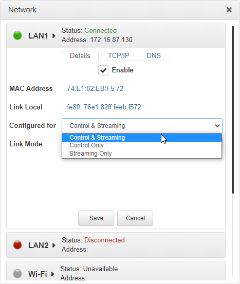
To enable or disable an interface select the Enable check-box when in Edit mode, then click Save. LAN1 and LAN2 are enabled by default. Please note that the Status LED color indicates the status of each network interface.
1.Any interface with a grey Status LED indication is disabled.
2.Any interface with a green Status LED indication is enabled and active.
3.Any interface with an amber Status LED indication is enabled and attempting to connect.
4.Any interface with a red Status LED indication is enabled and unavailable for some reason, e.g:
•Ethernet cable is not connected.
•Incorrect configuration, e.g. VLAN Identifier not correct.
•Wi-Fi access point is not selected.
Configure Link Mode
It is possible to configure the Ethernet link speed (10/100/1000/Auto) and whether each available interface operates in full-duplex or half-duplex modes.
1.Click the drop-down Link Mode arrow and select the preferred setting.
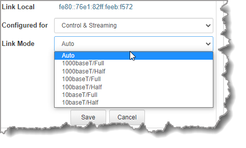
2.Click Save to store the new setting.
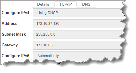
IPv4 Address Configuration
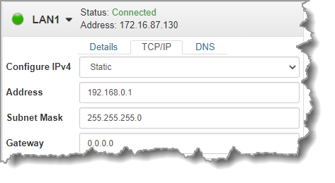
Click to select the TCP/IP tab in the Network panel to configure settings. The codec is capable of automatic DHCP address assignment, or manually configured static IPv4 address configuration via the Configure IPv4 drop-down menu. To ignore IPv4 settings select Off.
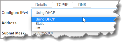
DHCP IP addresses are automatically assigned and can change each time you connect to your Internet Service Provider, or to your own local area network (LAN). By default the codec is configured for DHCP-assigned IP addresses.
Static IP addresses are fixed addresses that are recommended for studio installations, so that IP address dialing remains the same over time for incoming codec connections.
Click Save to store all configuration settings.
|
Important Note: The Subnet Mask is used by the TCP/IP protocol to determine whether a host is on the local subnet or on a remote network. The default Gateway is the router linking the codec's subnet to other networks. See your IT administrator for more details. |
IPv6 Address Configuration
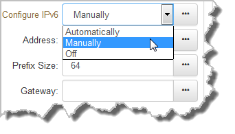
An IPv6 address is represented by 8 groups of 16-bit hexadecimal values separated by colons (:). The drop-down Configure IPv6 menu provides three address configuration options:
1.Automatically: An address is automatically assigned to the codec when you connect the codec to an IPv6 router. This process is similar to how an IPv4 DHCP address is assigned.
2.Manually: Select to enter static IPv6 address details.
3.Off: Select to ignore IPv6 address details.
|
Important Note: Select Off in the drop-down Configure IPv6 menu if you are not using IPv6 to connect to another device. This ensures your codec will attempt to connect using IPv4 at all times. |
Types of IPv6 Addresses
There are two types of addresses displayed in the IPv6 section:
1.IPv6 address (normally global): A router-allocated IP address with 'global' visibility, details of which are displayed in the Address, Prefix size and Gateway text boxes.
2.Link Local: A local address which can only be used to connect to another device directly over a LAN. This address is allocated by the codec internally based on MAC address details.
Auto Address Assignment
1.By default the codec is configured for connecting to an IPv6 router which automatically allocates IPv6 address details, as displayed in the following example.
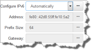
2.Click Save to store all configuration settings.
Manual IPv6 Address Assignment
1.To configure IPv6 address details into the codec manually, select Manually and enter details into the Address, Prefix and Gateway text boxes.
2.Click Save to store all configuration settings.
Specifying DNS Settings
It is possible to specify Domain Name Server (DNS) settings to allow easy look up of codecs within the specified DNS Addresses or Domains.
1.Select the DNS tab for the interface in the Network panel.
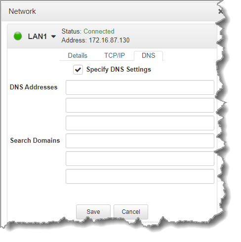
2.Click Edit to configure settings.
3.Click Save to store all configuration settings.
IP Via Mapping
When dialing over IP you can select the preferred interface to use when establishing a connection. By default Any is selected, which means the first available interface is used to dial a connection. The default Via interfaces in order of use when available are:
1.LAN1 Ethernet port (default Primary Via interface)
2.LAN2 Ethernet port (default Secondary Via interface)
3.Wi-Fi (default Tertiary Via interface)
|
Important Note: VLAN interfaces have features similar to physical Ethernet interfaces. However, your network administrator will need to configure VLAN support throughout your network for them to be supported in your codec. |
Reconfigure Default Primary, Secondary and Tertiary Interfaces
It is possible to reconfigure the default Primary (LAN1), Secondary (LAN2) and Tertiary (Wi-Fi) interfaces in the codec. As an example, you may want to select Primary as the dialing interface in a program and then copy this program onto multiple codecs. However, the actual primary interface used at each location can vary for each codec. For one codec it may be an Ethernet interface and for another it may be a Wi-Fi connection. This allows you to configure site-specific settings to suit the available network interfaces at different remote locations.
1.Open the HTML5 Toolbox Web-GUI and click Transport and then click IP Via Mapping to open this panel.
2.Click the drop-down arrow for each interface to select the preferred default setting.
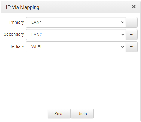
3.Click Save to store the configuration.
|
Important Note: Fuse-IP cannot be configured as a default Primary, Secondary or Tertiary Via. |
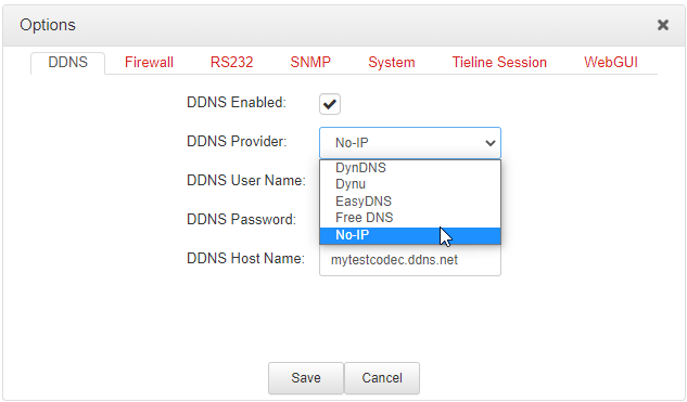
Configure Dynamic DNS (DDNS)
Dynamic DNS can be configured in the codec to allow the use of a host name to connect when using a dynamic IP address. To facilitate this a DDNS service is used to register a device's IP address to a host name, allowing a remote codec to dial to a host name. The host name will periodically be updated automatically as required, or when the dynamic IP address changes.
1.Open the HTML5 Toolbox Web-GUI and click Settings at the top of the screen, then click Options to display the Options panel.
2.Select DDNS and then click Edit to adjust settings.
3.Click Save to store the new configuration settings.
|
Important Note: •Supported DDNS providers are listed in the DDNS Provider drop-down menu. •Devices should be DDNS registered to public IP addresses. •The codec will utilize the System Internet interface order when contacting DDNS service providers. •Does not support connection to remote G3 codecs. •DDNS Host Name settings are unrelated to the Hostname setting accessed via the Options panel under Settings. |
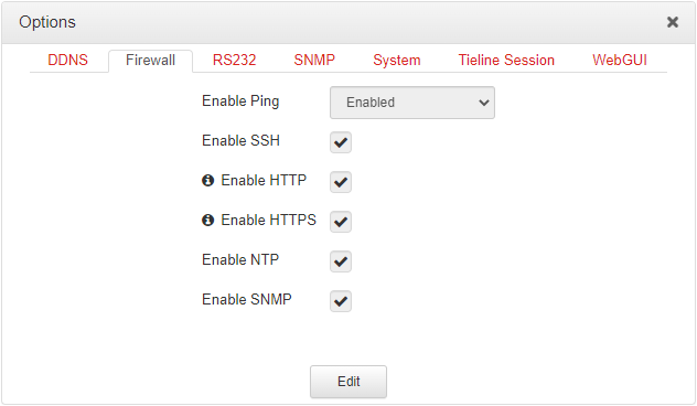
Configure Firewall Settings
The Firewall menu can be used to enable or disable a range of firewall-related network services, or limit ping to only work in a local subnet.
1.Open the HTML5 Toolbox Web-GUI and click Settings at the top of the screen, then click Options to display the Options panel.
2.Select Firewall and then click Edit to adjust settings.
3.Click Save to store the new configuration settings.
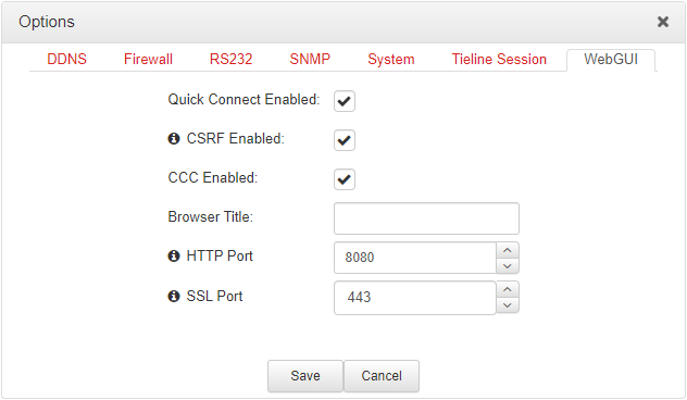
Configure Cross-Site Request Forgery
CSRF (Cross-Site Request Forgery) protection can be configured to protect the codec from CSRF attacks. To enable or disable this setting:
1.Open the HTML5 Toolbox Web-GUI and click Settings at the top of the screen, then click Options to display the Options panel.
2.Select WebGUI, then click Edit and select the CSRF Enabled check-box to enable this feature.
3.Click Save to store new configuration settings.
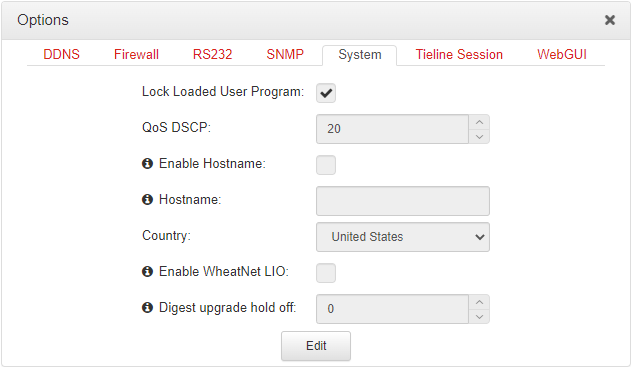
Configuring QoS
1.Open the HTML5 Toolbox Web-GUI and click Settings and then click Options to open the Options panel.
2.Select System and then click Edit. Click in the QoS DSCP text box and enter the preferred value.
3.Click Save to store configuration settings.
|
Important Note: Check with your IT administrator before changing this setting. By default the codec is configured for Assured Forwarding and more details about DSCP are available on Wikipedia at http://en.wikipedia.org/wiki/Dscp. |
