The following sections provide an overview of the different configuration panels available within the codec's HTML5 Toolbox Web-GUI. Navigate with the mouse pointer to the Menu bar at the top of the Web-GUI screen and click to select and open each panel in turn.

HTML GUI Menu Bar for Opening Panels
When you first open the HTML5 Toolbox Web-GUI the Program Manager panel, Connections panel and PPMs panel are loaded by default. If you retain cookies in your browser, any panels opened previously in the Web-GUI are automatically populated when logging in subsequently. The default panel view is displayed on login if cookies have been cleared.
The green Online indication in the top left-hand corner of the Toolbox Web-GUI indicates it is online and can be used for codec control. A red Offline indication is displayed when the codec is unavailable. The Upgrade symbol is displayed when a new firmware version is available for the codec. Open the Firmware panel in the Settings menu to upgrade the codec with new firmware.
|
Important Note: The AoIP menu and associated panels are for managing AoIP streaming (e.g. AES67, ST 2110-30, Livewire+, RAVENNA). Please see the AoIP Streaming Manual for configuration and streaming information. |

Features in Gateway and Gateway 4
Codec capabilities such as inputs, outputs and control port capabilities vary between different models. The following table outlines major feature differences between the most popular codec configurations available.
Product |
Feature |
Notification |
Gateway 4 |
PPM Meters |
8 PPMs on front panel display 4 inputs/outputs or 4 encoders/decoders |
Gateway 4 |
Inputs |
4 Channels in/out |
Gateway 4 |
Inputs |
Inputs 1-4 can be configured as analog or digital inputs (AES3 or AoIP) in pairs |
Gateway 4 |
Web-GUI Inputs panel |
4 inputs and PPMs displayed |
Gateway 4 |
Control Port GPIOs |
Supports 8 control port inputs and 8 opto-isolated outputs via a single DB25 CONTROL PORT I/O connectors |
Gateway 4 |
Software LIOs |
3 virtual inputs, 56 logical outputs, and 64 WheatNet Logic Inputs/Outputs |
Gateway 8/16 |
PPM Meters |
16 PPMs on front panel can display inputs/outputs/encoders/decoders |
Gateway 8/16 |
Inputs |
8-16 Channels In/Out (depending on codec configuration purchased) |
Gateway 8/16 |
Inputs |
Inputs 1-8 can be configured as analog or digital inputs (AES3 or AoIP) in pairs |
Gateway 8/16 |
Web-GUI Inputs panel |
8 - 16 inputs and PPMs displayed (depending on codec configuration purchased) |
Gateway 8/16 |
Control Port GPIOs |
Supports 16 control port inputs and 16 opto-isolated outputs via dual DB25 CONTROL PORT I/O connectors |
Gateway 8/16 |
Software LIOs |
3 virtual inputs, 48 logical outputs, and 64 WheatNet Logic Inputs/Outputs |
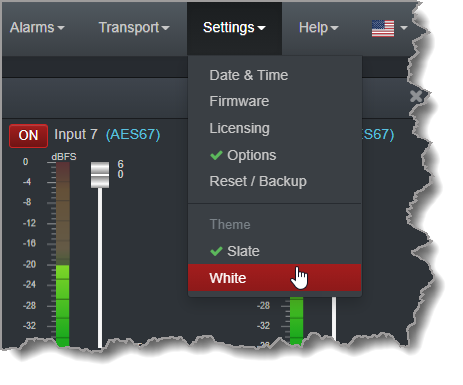
Adjusting the Theme
To adjust the Theme or 'skin' of the HTML5 Toolbox Web-GUI, navigate to the Menu bar at the top of the screen and click Settings, then click to select the preferred option. Note: this manual uses the White theme for most images.
Opening a Panel & Adjusting Size or Screen Position
Click an item in the Menu bar to display available panel options, then click to select and open a panel. New panels automatically open in the top left of the screen. A green Tick adjacent to a panel name in the menu signifies it is already open in the web-GUI.
Position the mouse pointer over a panel's Title bar and click and drag to move a panel and reposition it in a preferred screen position.
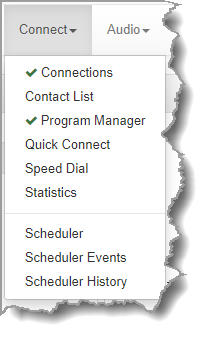
Connect Panels: Load & Connect Programs & Manage Audio Streams
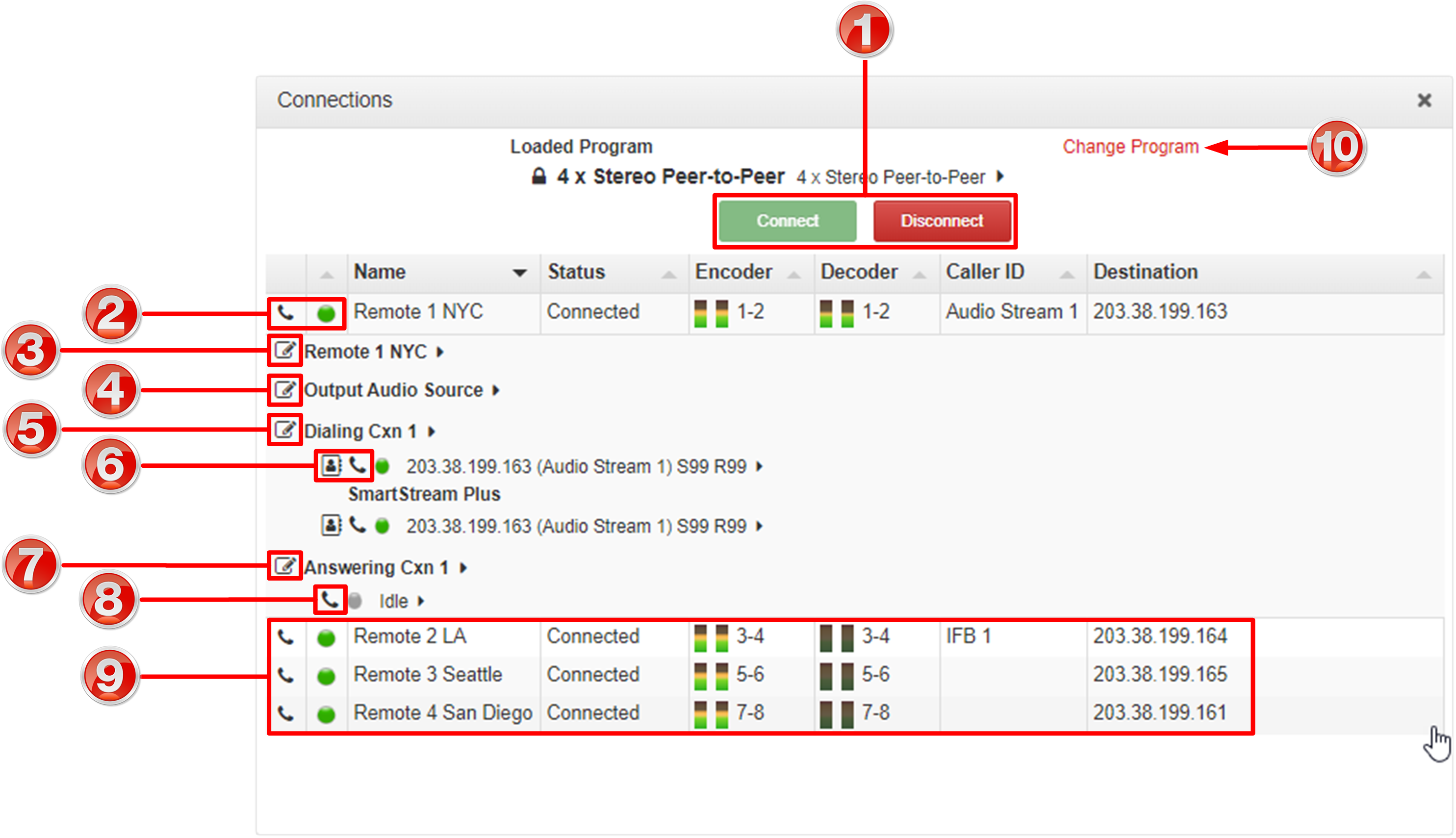
Connections Panel
|
Feature |
Description |
1 |
Program Connect / Disconnect buttons |
Click to connect or disconnect all audio streams in a program. |
2 |
Connect / Disconnect button and Connection State LED |
Click over stream details to expand stream information. Click again to collapse stream details. Click the Connect/Disconnect •Gray: Not in use •Green: Connected and stable (LQ greater than 70) •Yellow: Connected but connection quality is not stable (LQ 50 to 70) •Red: Connection establishing or problem with connection (LQ less than 50). LED flashes when establishing connection. Note: ISDN connections do not display the yellow LED state. |
3 |
Audio Stream Edit |
Click the Edit |
4 |
Output Audio Source Edit |
Click the Edit |
5 |
Connection Edit button (dialing connection) |
Click the Edit |
6 |
TieLink Contact List and Connection Connect / Disconnect button |
Click the Connect/Disconnect |
7 |
Answering connection Edit button |
Click to edit answering connection settings |
8 |
Answering Connection Disconnect button |
Click to disconnect an answering connection |
9 |
Additional Connections |
Other connections listed |
10 |
Change Program |
Click to unload the current program and load a new program. |
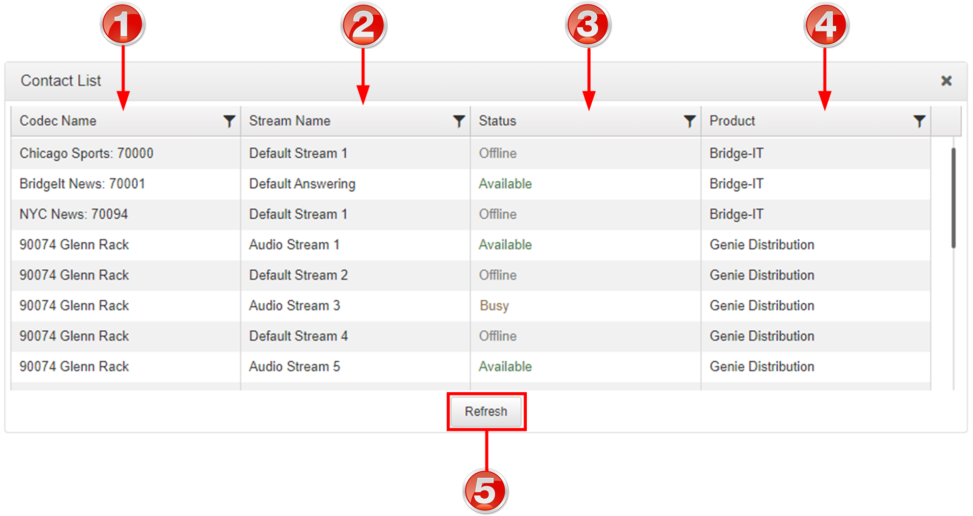
Contact List
|
Feature |
Description |
1 |
Codec Name |
The name given to a codec to identify it when a program is created |
2 |
Stream Name |
The name given to a stream to identify it when a program is created |
3 |
Status |
Displays the status of an audio stream, which can be Available, Busy or Offline |
4 |
Product |
Displays the model of codec |
5 |
Refresh |
Click Refresh to refresh the codec and stream list |
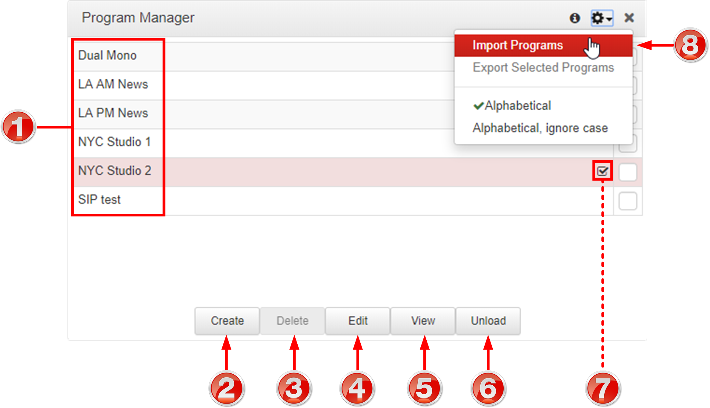
Program Manager Panel
|
Feature |
Description |
1 |
Program list |
The list of saved programs in the codec |
2 |
Create New Program button |
Click to create a new program using the program wizard. |
3 |
Delete Selected Programs button |
Click to delete all selected programs |
4 |
Edit Selected Program button |
Click to edit the selected program |
5 |
View Selected Program button |
Click to view configuration settings for a selected program |
6 |
Unload/Load program button |
Click to load or unload a program |
7 |
Loaded program symbol |
Symbol identifies the currently loaded program |
8 |
Import Programs and Export Selected Programs |
Click the Options menu to select and import previously saved programs or export selected programs as a .zip file |
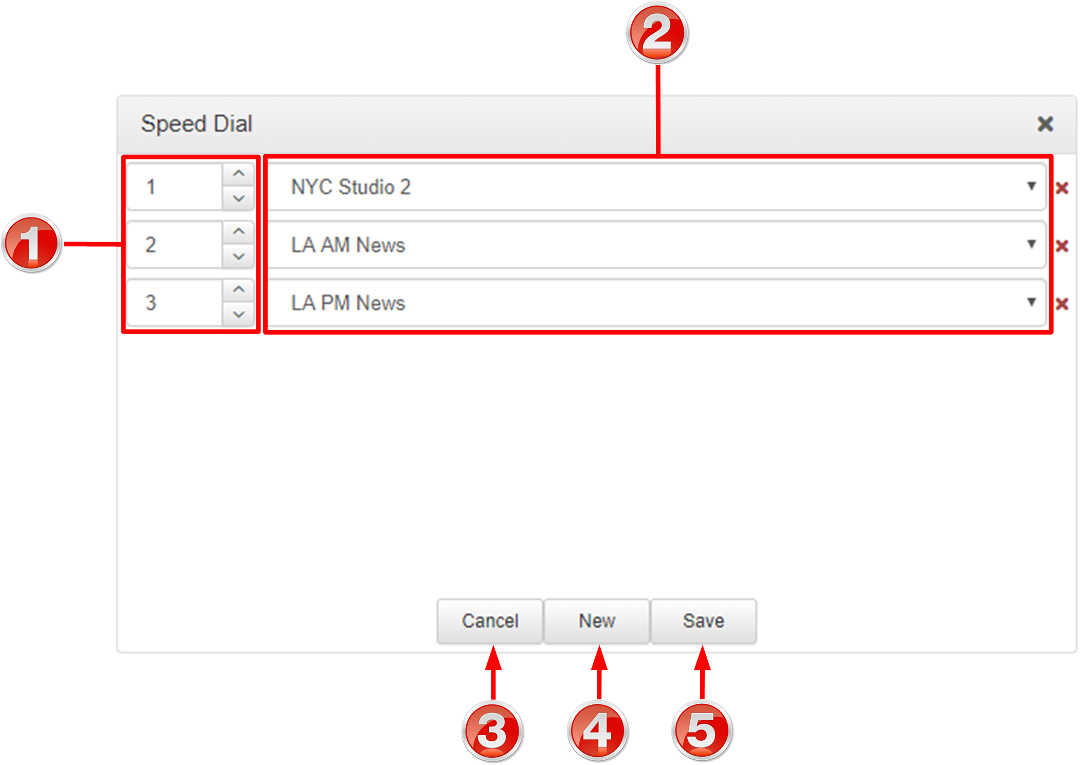
Speed Dial
|
Feature |
Description |
1 |
Speed dial numbers |
The number allocated for each speed dial configured |
2 |
Speed dial program |
Select the program to associate with a speed dial number |
3 |
Cancel button |
Click to cancel pending changes |
4 |
New button |
Click to create a new speed dial |
5 |
Save button |
Click to save configuration changes |
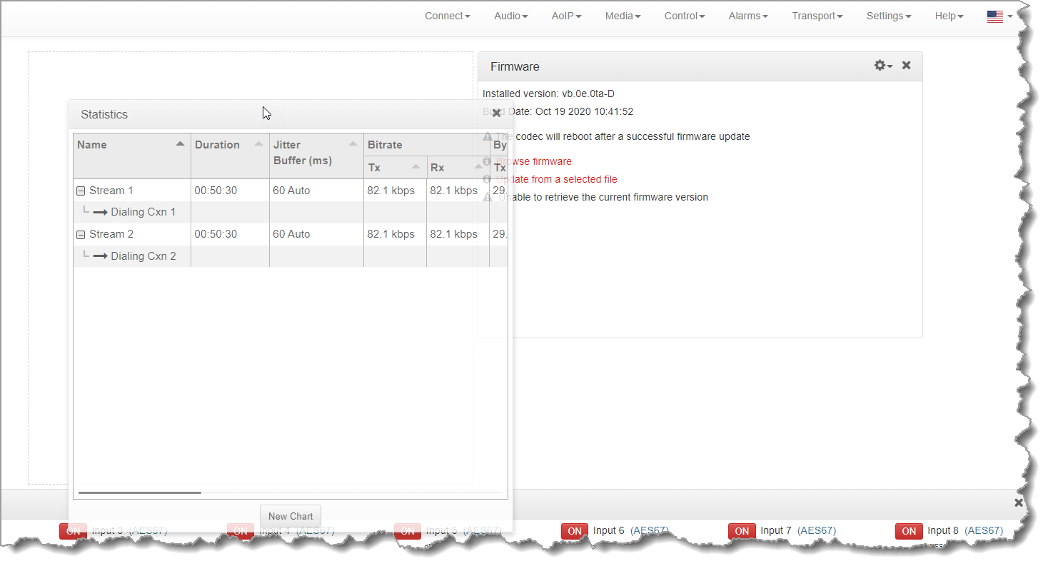
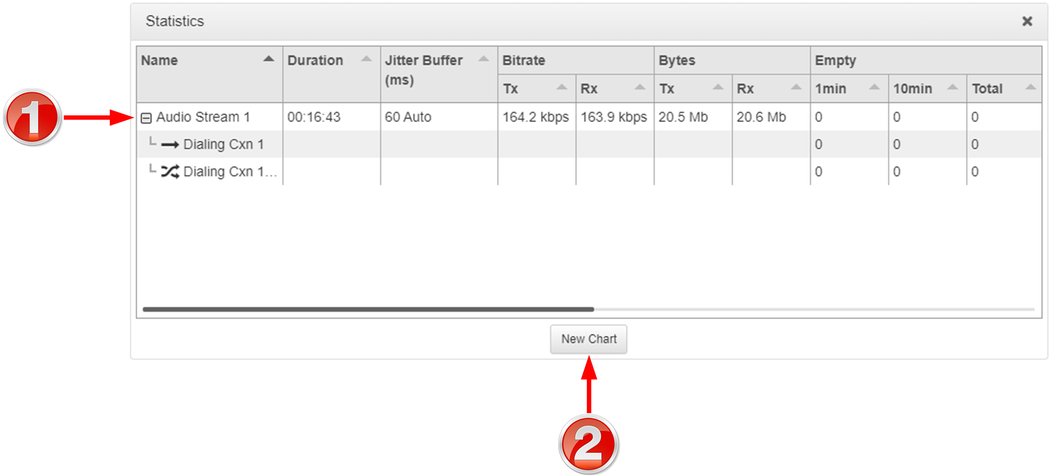
Statistics Panel
|
Feature |
Description |
1 |
Expand/Collapse |
Click to show/hide audio stream statistics, including packet arrival data info. |
2 |
New Chart button |
Click the New Chart button to select a Data Series and create a customized Statistics panel. |
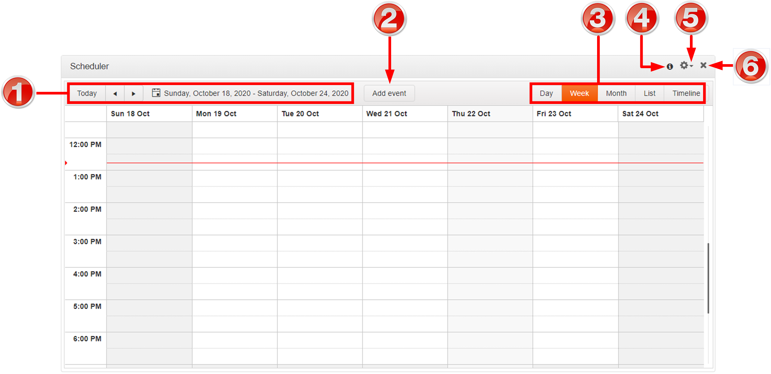
Scheduler Panel
|
Feature |
Description |
1 |
Date selection |
Select the days you wish to view in the scheduler. |
2 |
Add event button |
Click to create a new scheduled event. |
3 |
View type |
Click to select the timeframe or timeline view of scheduled events. |
4 |
Information symbol |
Hover over the Information symbol to view Scheduler panel information. |
5 |
Options menu |
Click the Options symbol |
6 |
Close button |
Click to close the panel. |

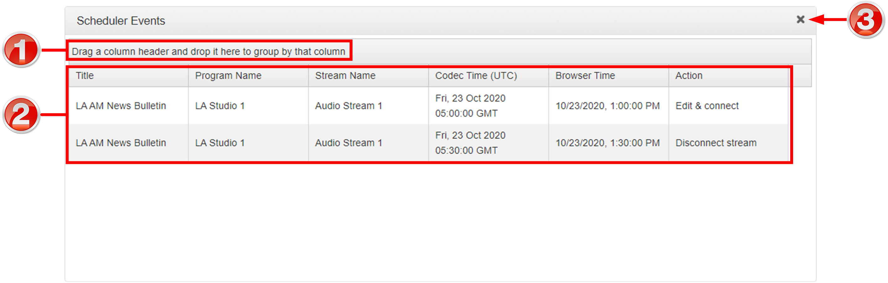
Scheduler Events Panel
|
Feature |
Description |
1 |
Grouping |
Drag and drop a column header to group scheduled events by that column, e.g. Codec Time. |
2 |
List of scheduled events |
View scheduled events in a list view |
3 |
Close button |
Click to close the panel. |
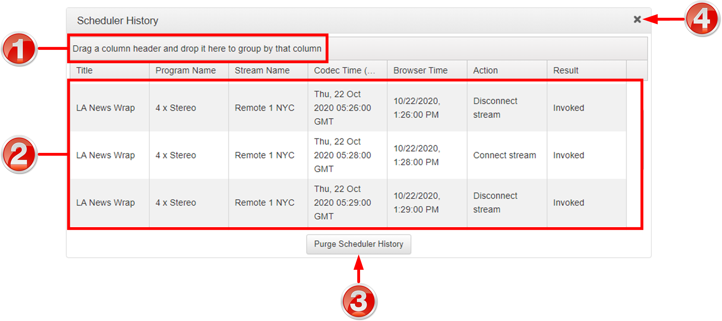
Scheduler History
|
Feature |
Description |
1 |
Grouping |
Drag and drop a column header to group event history by that column, e.g. Codec Time. |
2 |
Event History List |
View the codec's history of scheduled events. |
3 |
Purge Scheduler History button |
Click to clear all event history displayed. |
4 |
Close button |
Click to close the panel. |
Audio Menu Panels
|
Important Note: Tieline codecs have different input/output configurations, therefore the images shown in this section may not reflect the number of inputs and outputs displayed in your codec Web-GUI. |

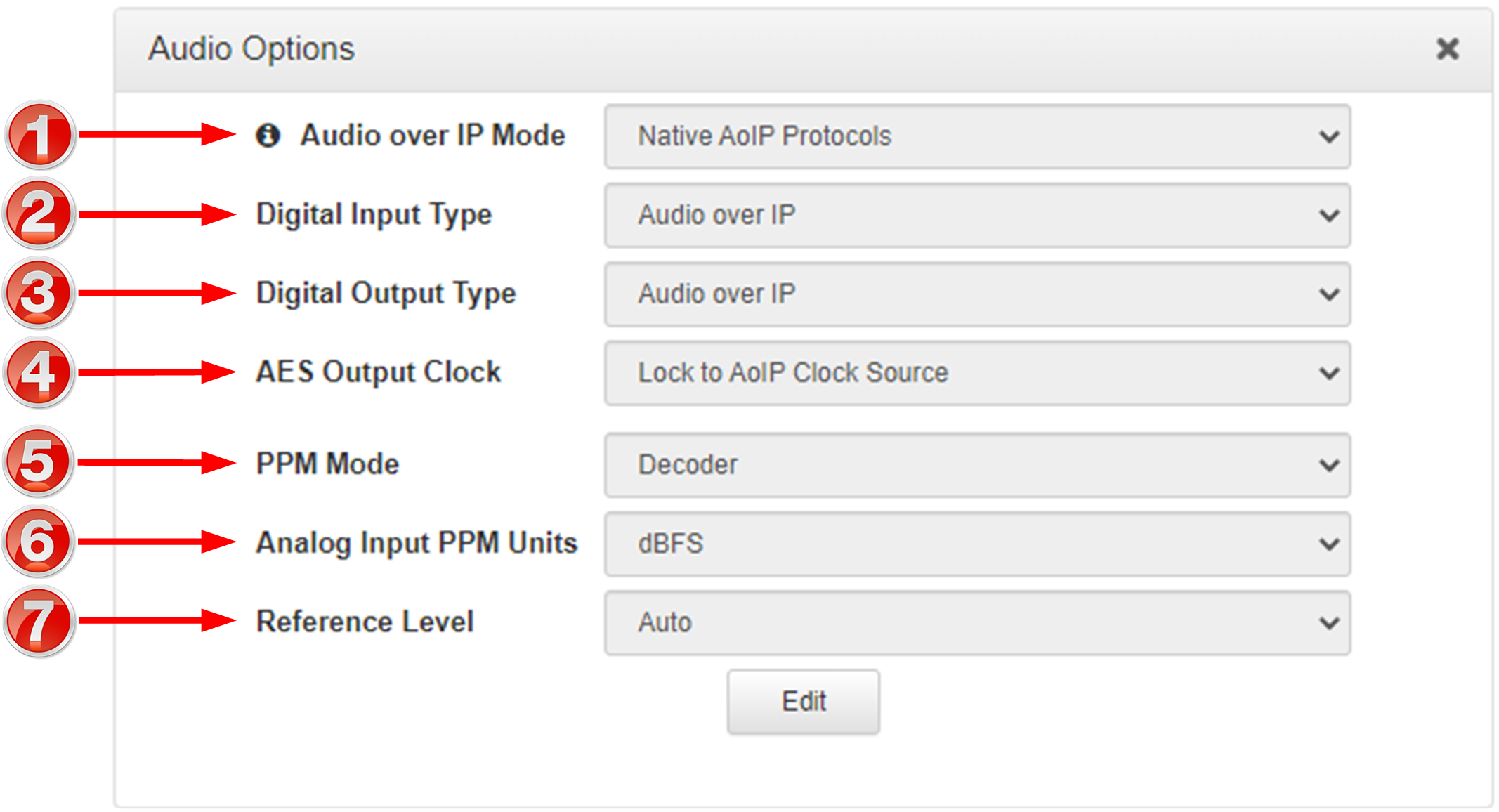
Audio Options
|
Feature |
Description |
1 |
Audio over IP Mode
|
If an optional WheatNet-IP card is installed in the codec select WheatNet-IP. Select Native AoIP Protocols as the AoIP mode when streaming with natively supported protocols, e.g. AES67, ST 2110-30, Livewire+ and RAVENNA. Note: this setting is only visible if a WheatNet-IP card or Dante card (future feature) is installed. |
2 |
Digital Input Type |
Select either AES3 or Audio over IP as the Digital Input Type for the codec. This setting is global for all digital inputs. |
3 |
Digital Output Type |
Select either AES3 or Audio over IP as the Digital Output Type for the codec. This setting is global for all digital outputs. |
4 |
AES Output Clock |
The sample rate of the AES3 output is configured using the clock source which sets the sample rate frequency of all AES3 output signals. AES67/ST2110-30/Livewire derives the sampling clock from a primary leader clock or Livewire clock over the network and the AES3 Output Clock source uses the Lock to AoIP Clock Source setting if either the Digital Input Type or Digital Output Type is set to AoIP. If a WheatNet-IP card is installed, and the Digital Input Type or Digital Output Type is set to Audio over IP, then the AES3 Output Clock Source is forced to Lock to WNIP Clock. |
5 |
PPM Mode |
PPM metering can be adjusted to display inputs, outputs, encoders and decoders with this setting. |
6 |
Analog Input PPM Units |
Use this setting to change the analog input PPM meter unit of measurement from dBFS (default) to dBU |
7 |
Reference Level |
The codec will automatically adjust the reference level to suit G5 and G3 codecs, or Report-IT. The reference level can also be preconfigured using this setting. |
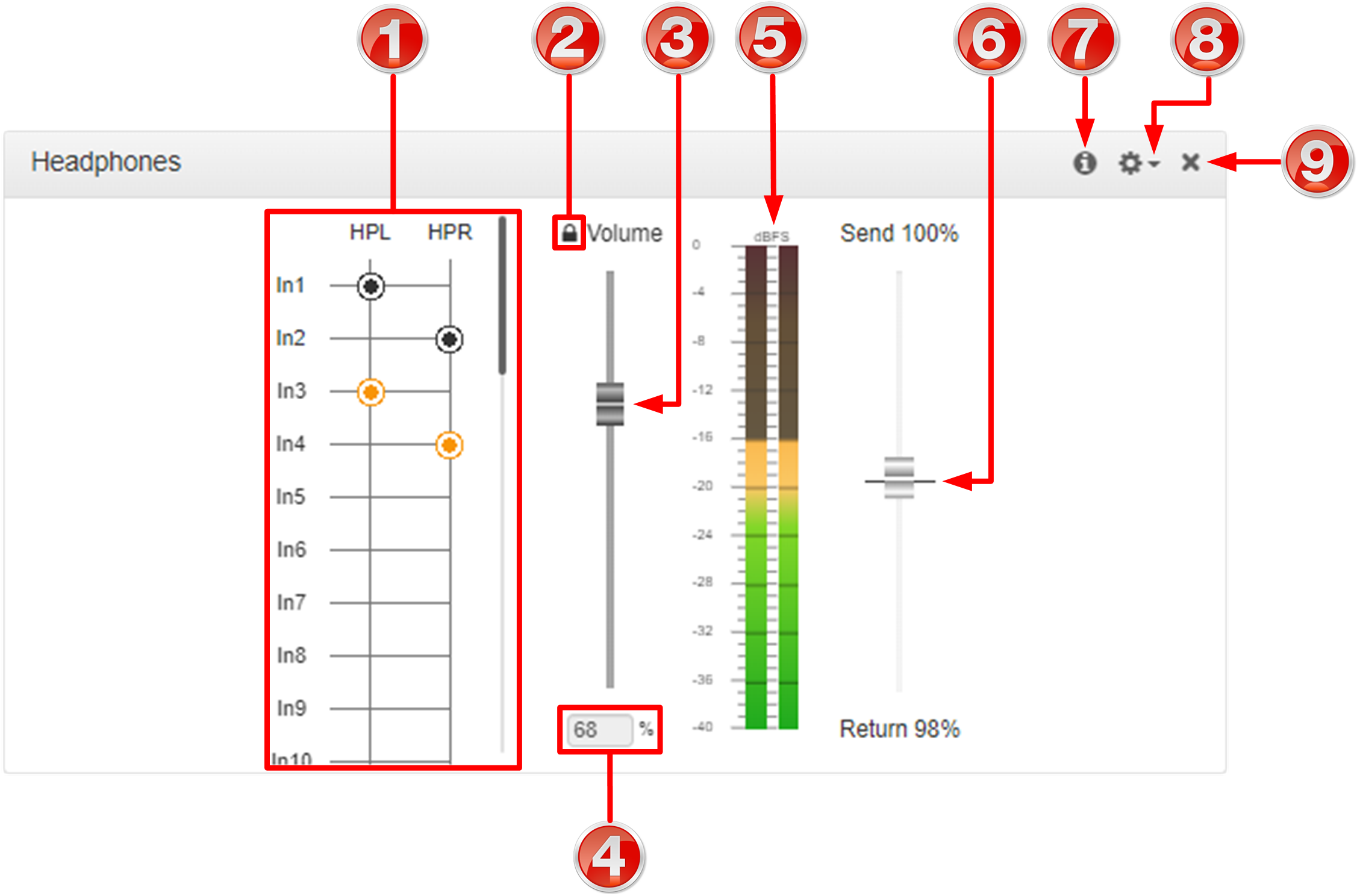
Headphones Panel
|
Feature |
Description |
1 |
Headphone Matrix |
Select inputs and decoders to monitor outgoing and incoming audio |
2 |
Headphone Adjust Lock |
Click the Headphone Adjust Lock symbol to enable adjustment of headphone output volume. WARNING: This may adjust the headphone volume of someone listening to a headphone output at a remote location. Extreme caution is recommended when this setting is enabled. High headphone levels can cause hearing loss! |
3 |
Headphone Volume Slider |
Slider used to increase and decrease headphone output volume. WARNING: This may adjust the headphone volume of someone listening to a headphone output at a remote location. Extreme caution is recommended when this setting is enabled. High headphone levels can cause hearing loss! |
4 |
Headphone Gain % |
Headphone gain expressed as a percentage |
5 |
Headphone Level PPMs |
View PPM levels of input/decoder audio fed to the headphone output |
6 |
Send/Return slider |
Use the Send/Return slider to adjust the balance between the mix of incoming (return/decoder) audio and outgoing (send/input) audio fed to the headphone output |
7 |
Information symbol |
Hover over the Information symbol to view Scheduler panel information |
8 |
Options menu |
Click the Options symbol |
9 |
Close button |
Click to close the panel |
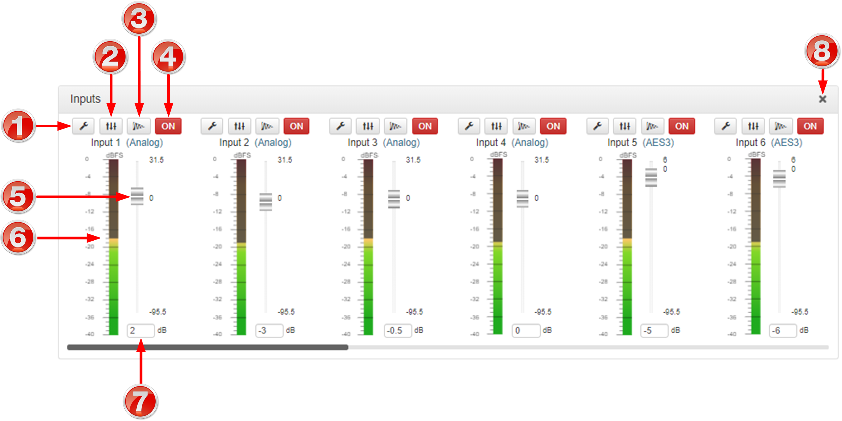
Inputs Panel
|
Feature |
Description |
1 |
Settings button |
Click to adjust input Name, Type, Polarity Inverted and IGC settings |
2 |
EQ button |
Click to enable and adjust 10 band EQ settings for individual inputs |
3 |
Compressor button |
Click to enable the input compressor on each input |
4 |
On/Off button |
Click to toggle an input on or off |
5 |
Input Sliders/Faders |
Input gain control sliders/faders. Adjust input gain in +/- 0.5dB increments |
6 |
Input PPM meter |
Input PPM meter |
7 |
Input gain adjustment |
Enter a dB value to adjust input gain in 0.5dB increments |
8 |
Close button |
Click to close the panel |
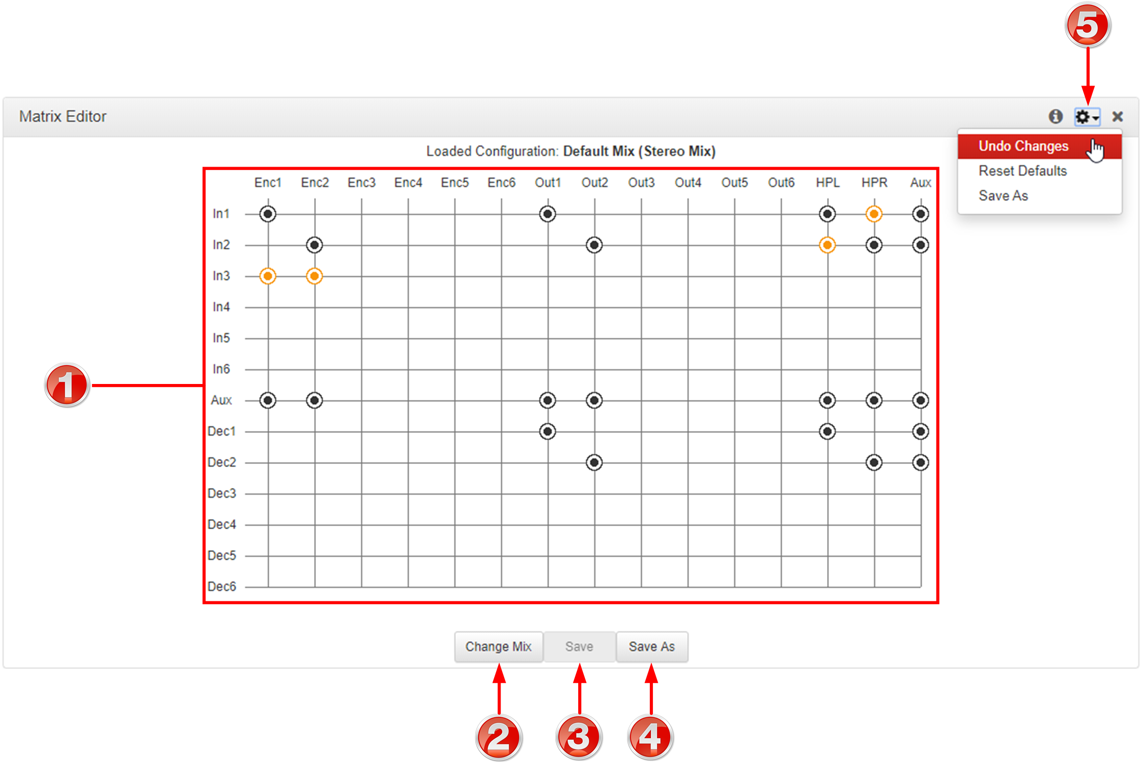
Matrix Editor Panel
|
Feature |
Description |
1 |
Matrix Editor crosspoint matrix |
Click to select and deselect audio crosspoints to customize routing. |
2 |
Change Mix |
Click to select the default or Custom matrix mix to view and edit. Options include Load, Delete and Rename a mix |
3 |
Save |
Click to save changes to a custom matrix mix |
4 |
Save as |
Click to save as a new custom matrix mix |
5 |
Options menu |
Menu options available to undo any changes, reset the mix to the factory default matrix mix for the program, or save as a new mix. |
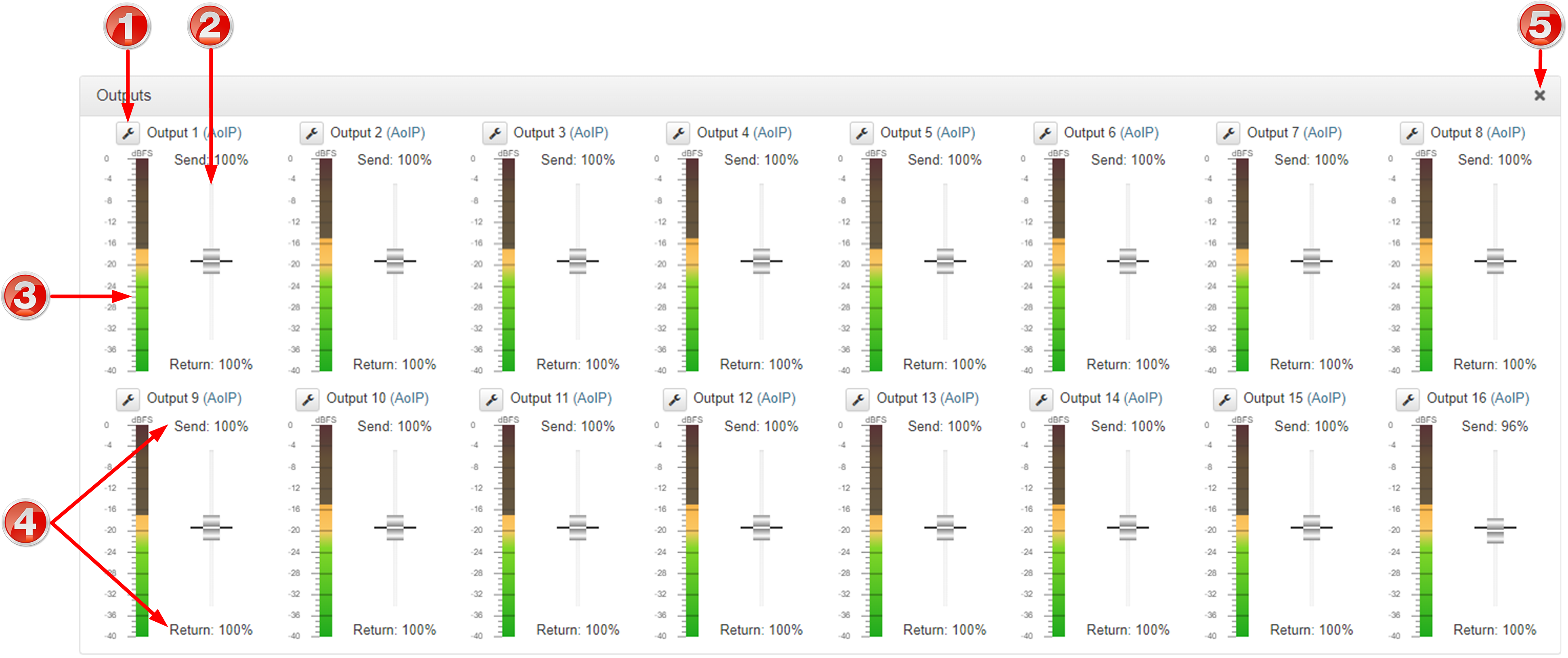
Outputs Panel
|
Feature |
Description |
1 |
Settings |
Select analog or digital as the output type. Note: configure the global digital output type via Setting > Audio Options > Dig.Output Type > [select AoIP or AES3]. |
2 |
Send/Return slider |
Use the Send/Return slider to adjust the balance between the mix of incoming (return/decoder) audio and outgoing (send/input) audio fed to each codec output |
3 |
Output PPM meter |
Output PPM meter |
4 |
Send/Return indications |
Balance of send and return audio included in the mix for each output (expressed as a percentage) |
5 |
Close button |
Click to close the panel |
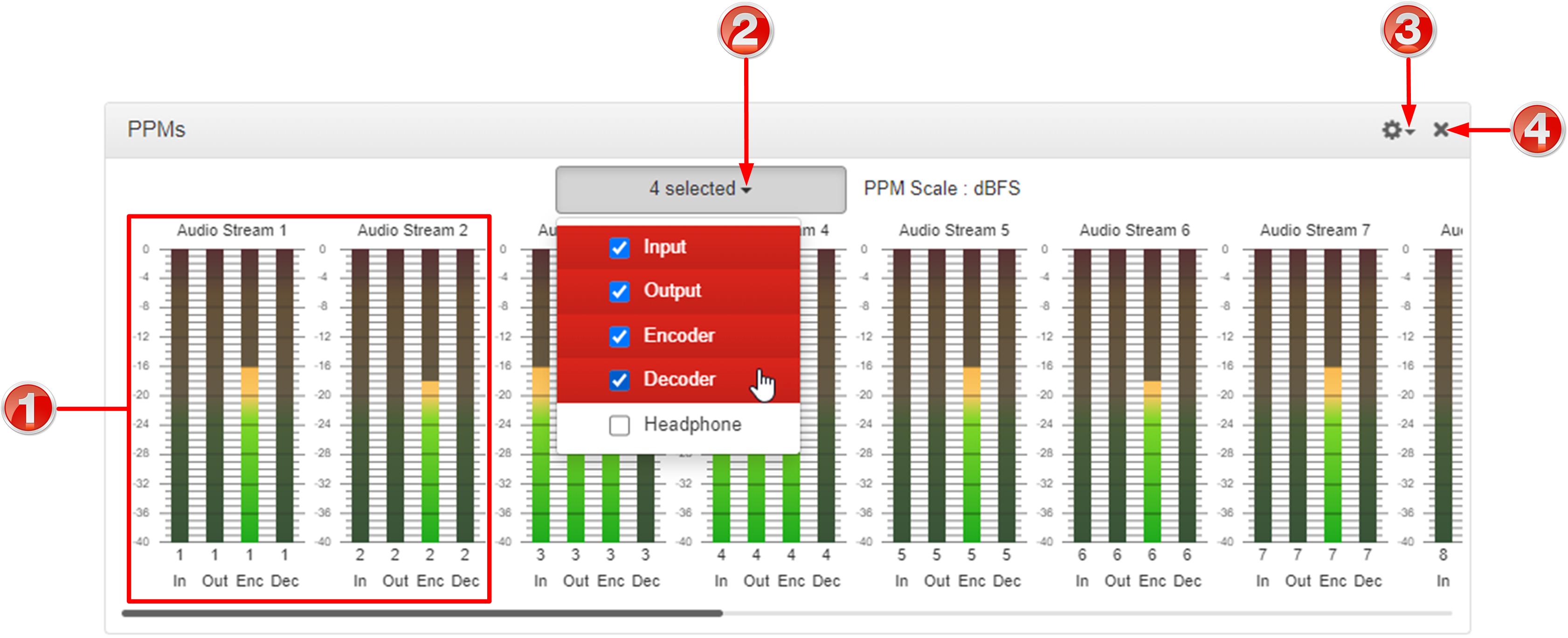
PPMs Panel
Note: Click and drag the bottom right-hand corner to expand the panel.
|
Feature |
Description |
1 |
PPMs |
Audio stream PPMs grouped |
2 |
PPM Select menu |
Selectable audio stream PPM metering options using dBFS audio scale |
3 |
Options menu |
Options menu allows users to group PPMs by stream, or by type, e.g. input, output, encoder, decoder and headphone. |
4 |
Close button |
Click to close the panel. |
|
Important Note: Codec front panel PPMs 1-6 and PPMs in the PPMs panel always reflect the default program settings and do not display customized mix adjustments using the Matrix Editor. |
Media Menu
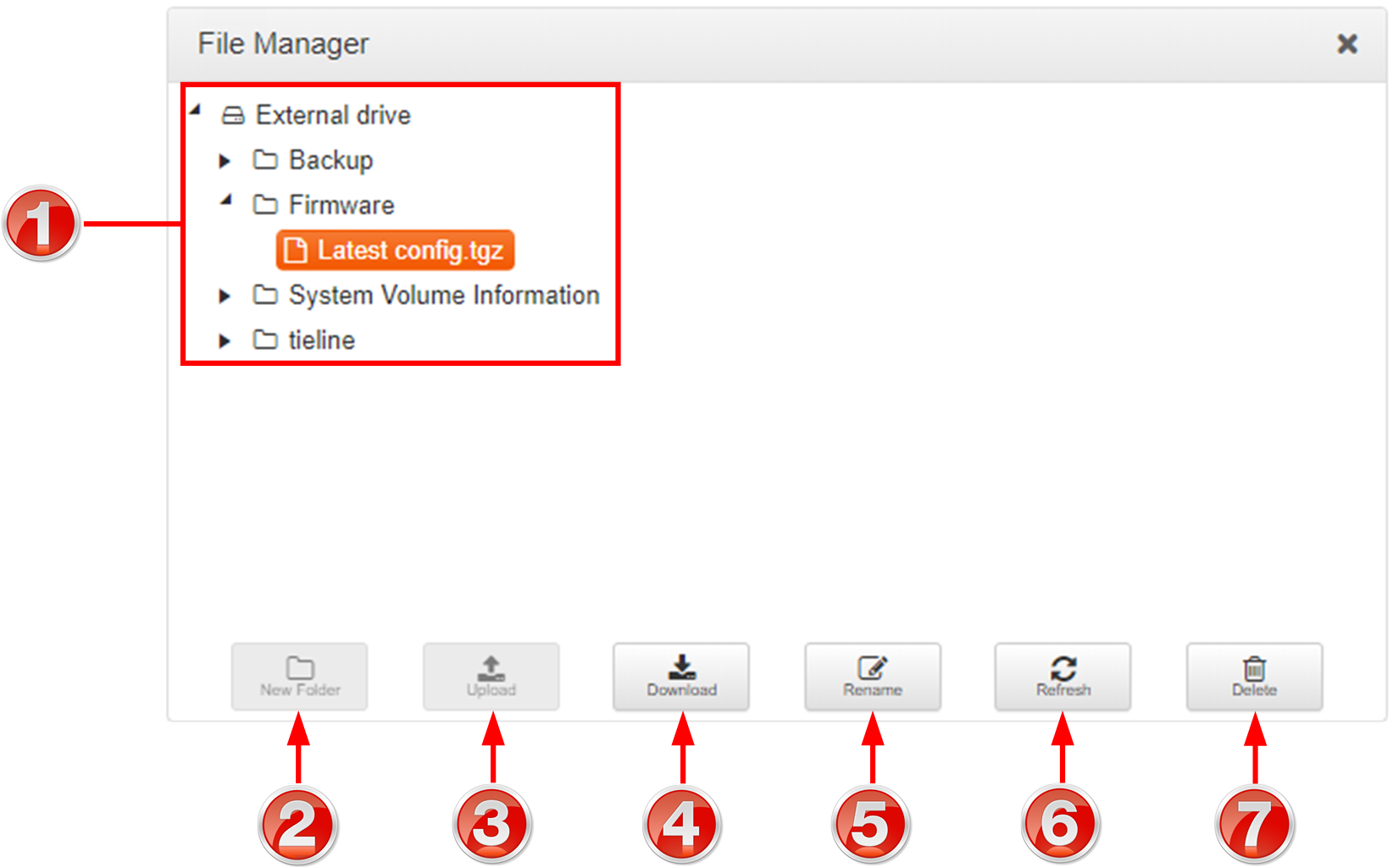
File Manager
|
Feature |
Description |
1 |
Folder and File View |
View all folders and files on an external drive / removable media |
2 |
New Folder |
Select the drive or a folder and then click to create a new sub-folder |
3 |
Upload |
Click to select and upload a new file onto removable media |
4 |
Download |
Click to download a file onto removable media |
5 |
Rename |
Click to rename a selected file or folder |
6 |
Refresh |
Click to refresh the panel and view all files and folders |
7 |
Delete |
Click to delete a selected file or folder |
Control Menu
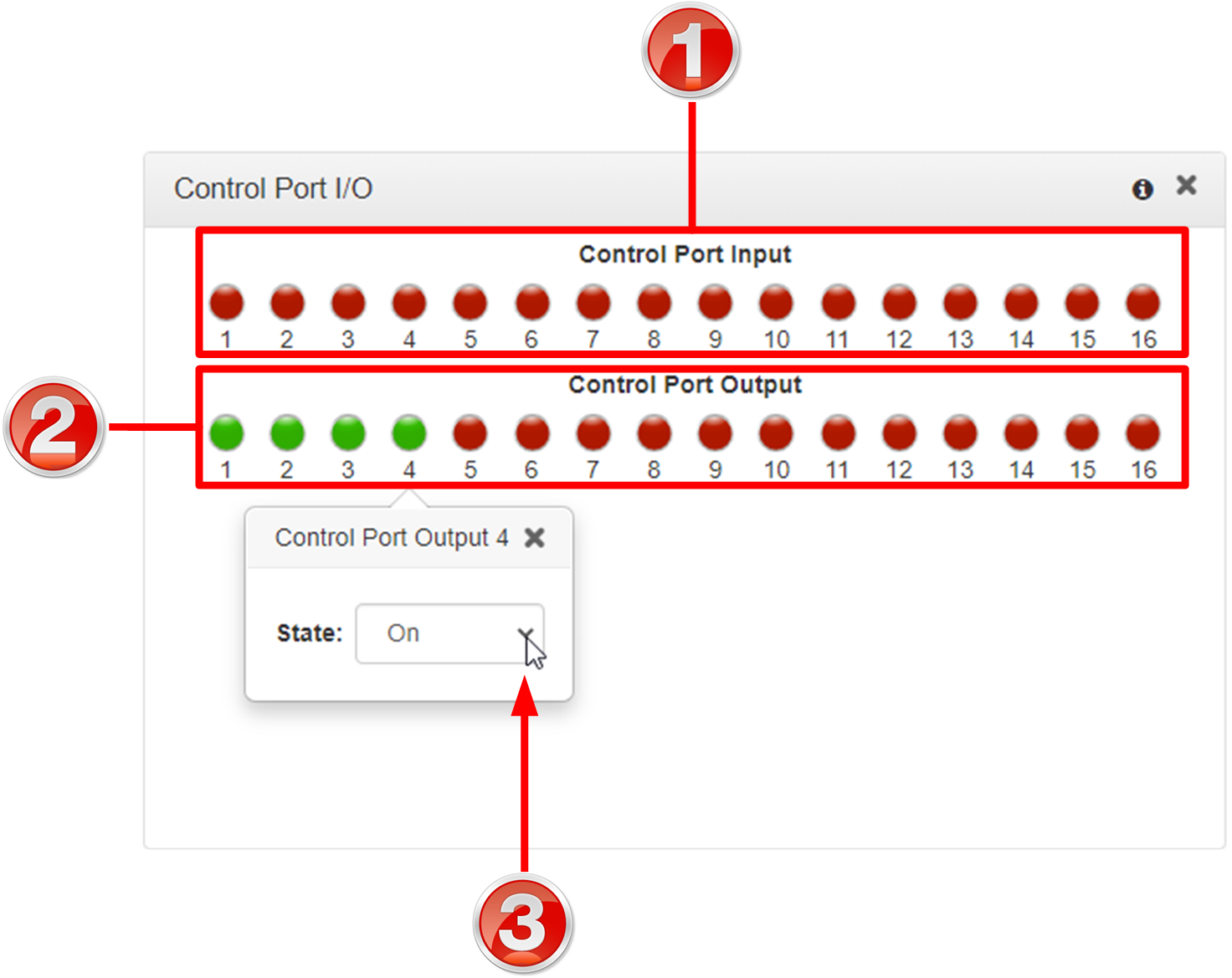
Control Port I/O
|
Feature |
Description |
1 |
Control Port Input state |
Displays the state of a control port input |
2 |
Control Port Output |
Displays the state of a control port output |
3 |
State |
Click a Control Port Output to change the On/Off state |
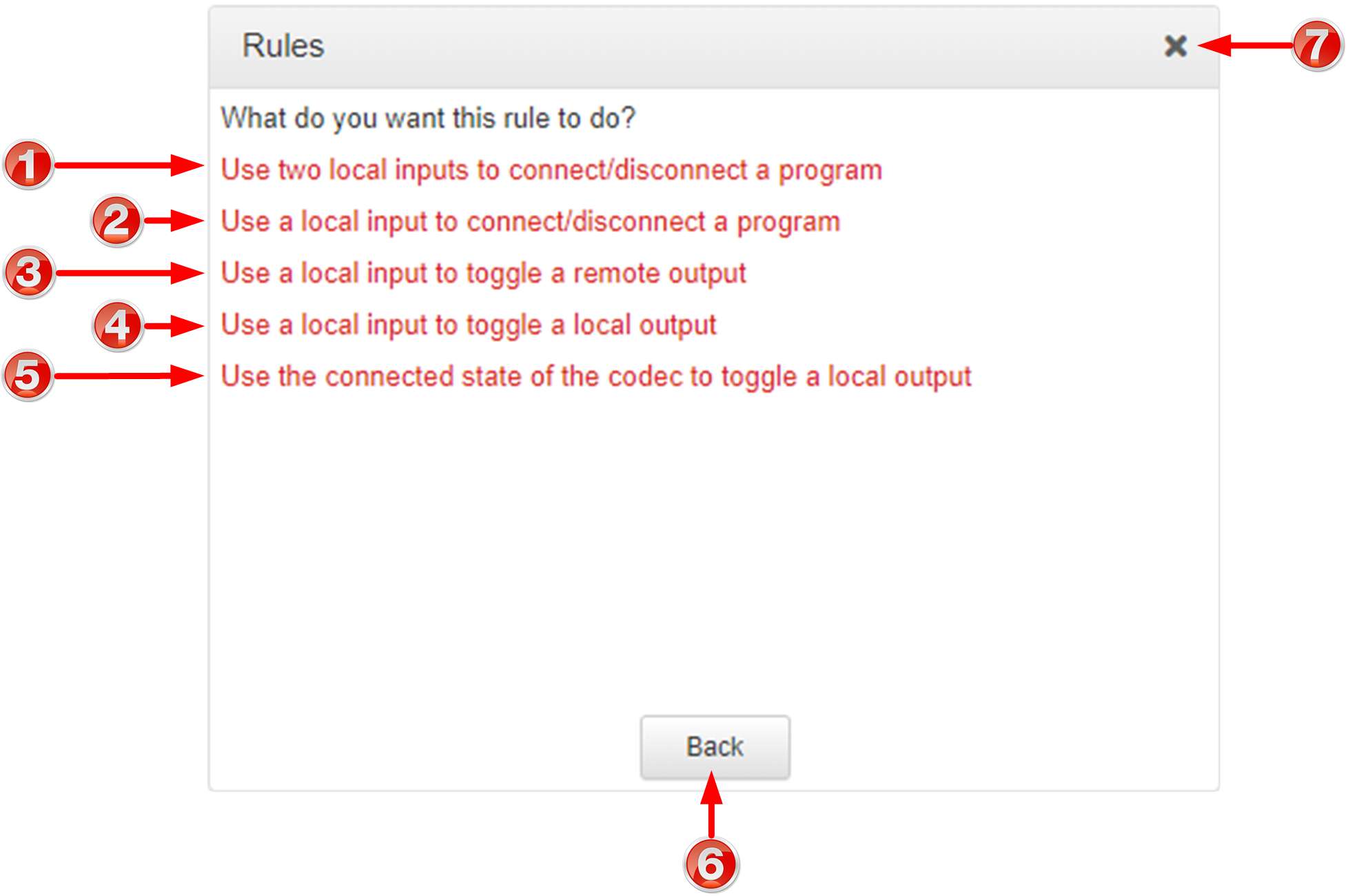
Rules Panel
|
Rule |
Description |
1 |
Use two local inputs to connect/disconnect a program |
Click to configure connection and disconnection after different relay inputs are switched ON. |
2 |
Use a local input to connect/disconnect a program |
Click to configure connection and disconnection by toggling an input. |
3 |
Use a local input to toggle a remote output |
Click to configure a local relay input to synchronize with the state of a remote relay output. |
4 |
Use a local input to toggle a local output |
Click to configure a local relay input to synchronize with the state of a local relay output. |
5 |
Use the connected state of the codec to toggle a local output |
Click to configure a relay to toggle based on connection status. |
6 |
Back / Add New Rule button |
Click to add a new rule, or exit the rule creation function. |
7 |
Close button |
Click to close the panel. |
Alarms Panels: Configure & Monitor Alarms
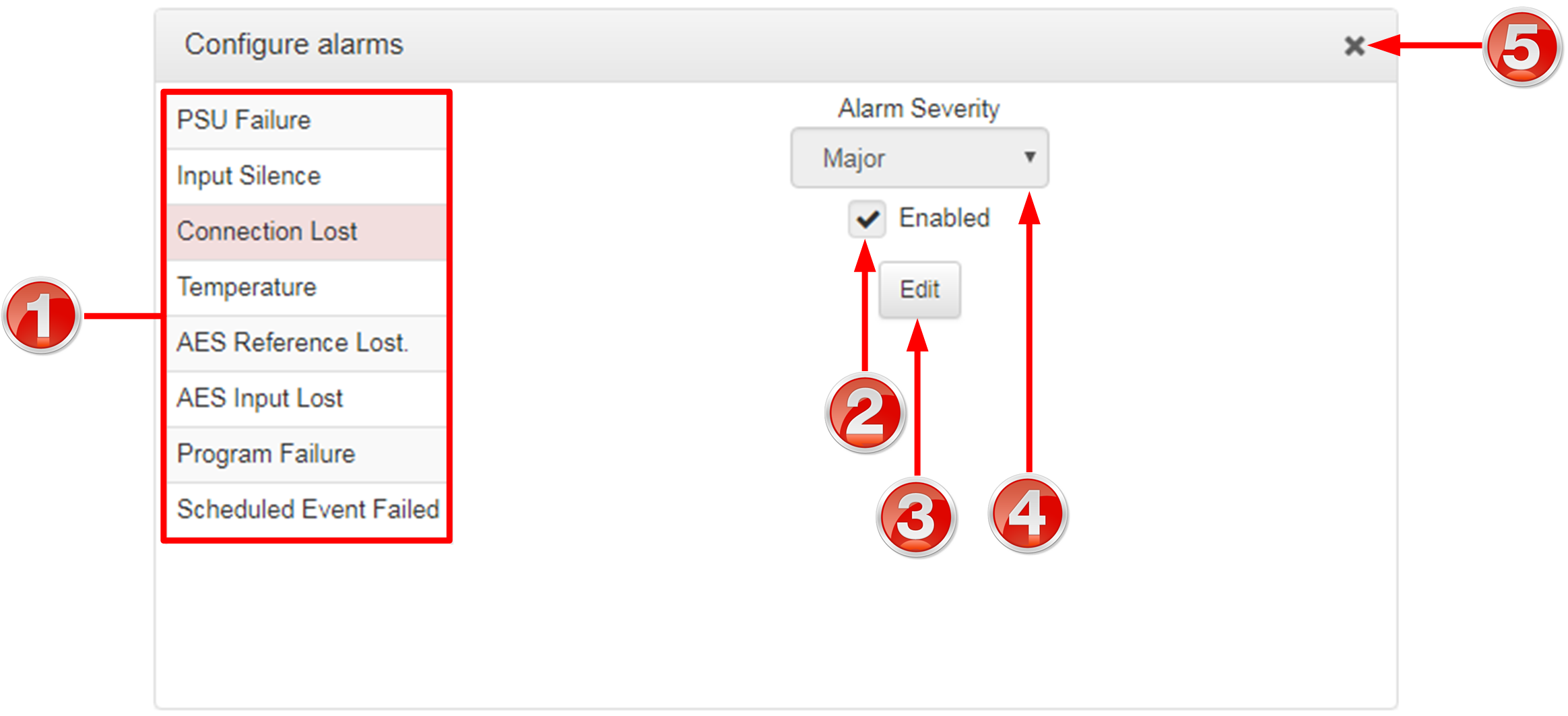
Configure Alarms Panel
|
Feature |
Description |
1 |
List of alarm types |
Click to select an alarm type to configure. |
2 |
Enable Alarm check-box |
Click the Enabled check-box to enable the currently selected alarm. |
3 |
Edit / Save button |
Click to edit an alarm, or save configured alarm settings when in edit mode. |
4 |
Alarm Severity Setting |
Click the drop-down arrow to select an alarm severity setting. |
5 |
Close button |
Click to close the panel |
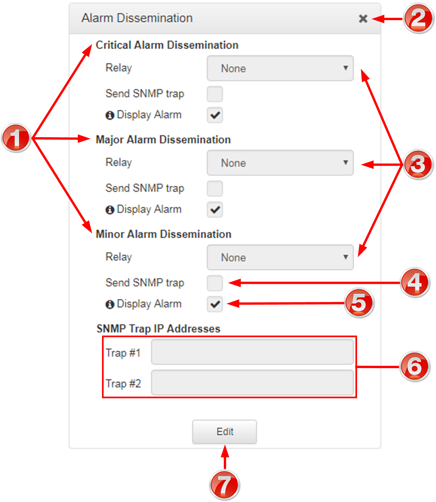
Alarm Dissemination Panel
Alerts for each alarm severity level are configured using the Alarm Dissemination panel.
|
Feature |
Description |
1 |
List of alarm severity levels |
Click to select an alarm severity level to configure it. |
2 |
Front panel alarm & Toolbox check-box |
Select the check-box (default enabled) to deliver front panel ALARM LED notifications and HTML5 Toolbox Web-GUI alarm notifications. |
3 |
Close button |
Click to close the panel. |
4 |
Relay drop-down selection |
Click the drop-down arrow to select a relay to open when an alarm using the current severity level is activated. |
5 |
SNMP Trap Target text-box |
Click in the text box in edit mode to enter the SNMP trap target for alarms using the currently selected severity level. |
6 |
Edit / Save button |
Click to edit alarm dissemination settings, or save configured settings when in edit mode. |
7 |
Send SNMP trap check-box |
Select the check-box to enable SNMP traps to be sent (for alarms using the selected severity level). |
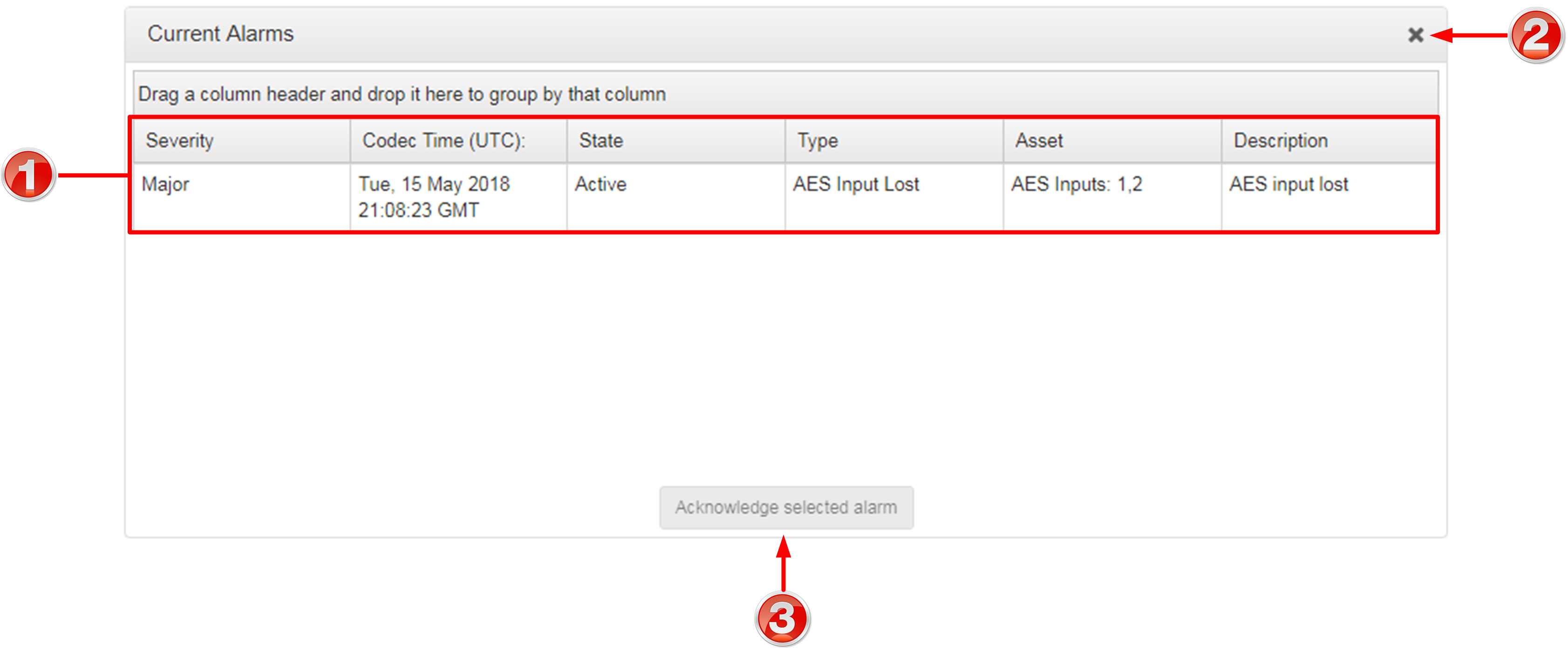
Current Alarms
|
Feature |
Description |
1 |
Current alarm description |
View a list of active alarms in the codec |
2 |
Close button |
Click to close the panel |
3 |
Acknowledge selected alarm button |
Click to acknowledge a selected alarm. |
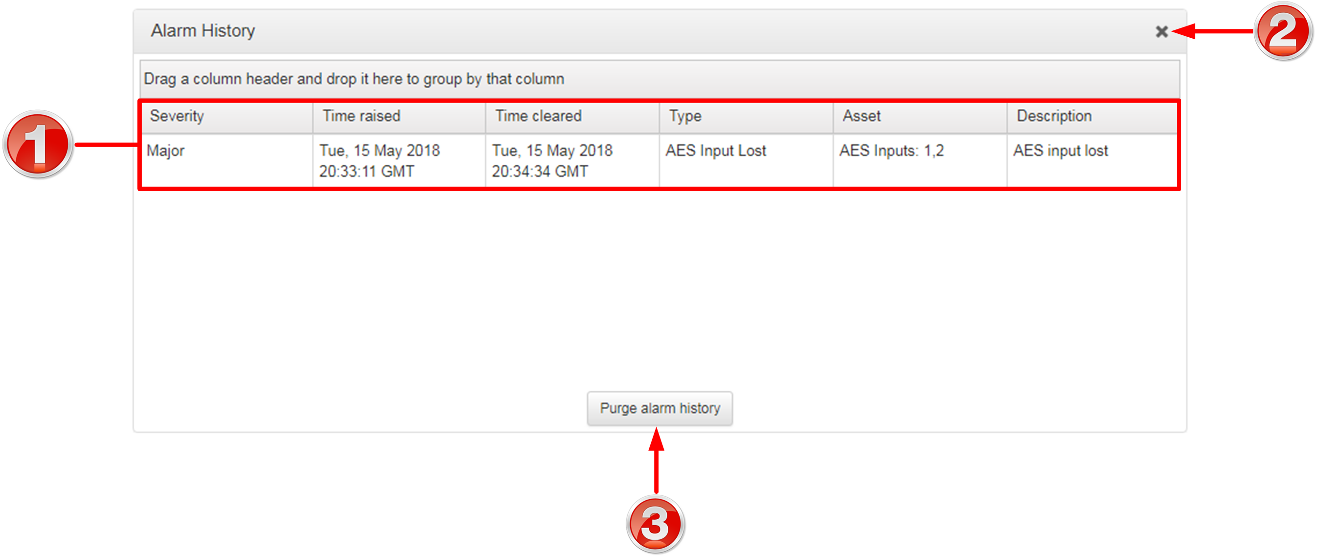
Alarm History
|
Feature |
Description |
1 |
Alarm history description |
View the history of previous alarms in the codec. |
2 |
Close button |
Click to close the Alarms panel. |
3 |
Purge Alarm History button |
Click to clear the alarm history. |
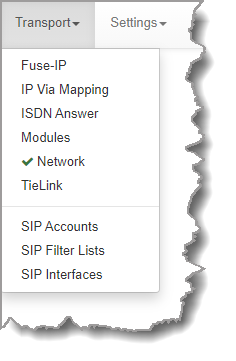
Transport Panels
There are several Transport panels which can be opened in the Web-GUI. Each panel provides specific transport-related configuration settings and options. Click to select and open each panel. |
|
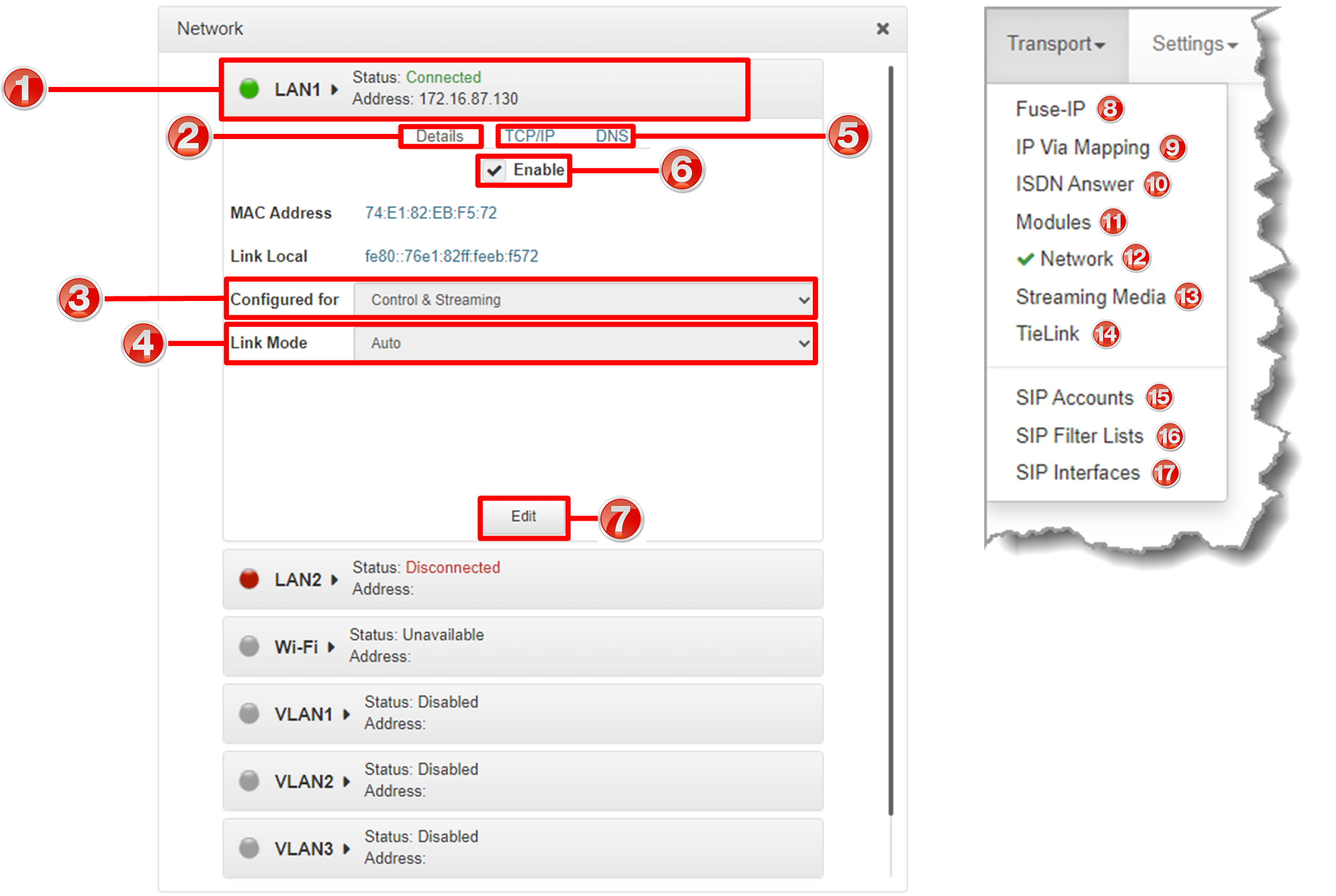
As an example, the Network panel is displayed with network interface configuration options. A brief description of the other panels is also provided.
|
Feature |
Description |
1 |
Network interface |
Click to select, expand and view configuration, and edit network configuration settings for Ethernet, Wi-Fi and VLAN interfaces. |
2 |
Details tab |
Displays configuration options for the selected network interface, plus other device details. |
3 |
Control/Streaming |
Select Control and/or Streaming options for the selected interface. |
4 |
Link Mode |
Configure the Ethernet, VLAN or Wi-Fi link speed (10/100/1000/Auto) and whether an interface will operate in Full-Duplex or Half-Duplex mode. |
5 |
TCP/IP and DNS tabs |
Select the TCP/IP tab to configure IPv4/IPv6 address details. Select the DNS tab to specify DNS addresses and domains to search. |
6 |
Enable check-box |
Selectable check-box to enable/disable an interface. |
7 |
Save/Undo button |
Click Save to store settings, or click Undo to revert to previously configured settings. |
8 |
Fuse-IP |
Click to open the Fuse-IP panel and configure Fuse-IP bonding. |
9 |
IP Via Mapping |
Configure default Primary, Secondary and Tertiary interfaces. |
10 |
ISDN Answer |
Click to open the panel and configure ISDN Answering settings if an ISDN module is installed. |
11 |
Modules |
Click to edit hardware module configuration settings. |
12 |
Network |
Click to open the Network panel and configure network settings. |
13 |
Streaming Media |
Click to configure HTTP streaming media settings for a local Icecast server running on the codec. Enable a local Icecast server and specify the Icecast Server Port. |
14 |
TieLink |
Click to view the TieLink panel to enable, disable and prioritize interfaces, configure ports and Fuse-IP interfaces, and configure STUN server settings. |
15 |
SIP Accounts |
Click to open the panel and edit SIP account settings. Up to 6 SIP accounts are supported. |
16 |
SIP Filter Lists |
Add trusted network codecs to the URI Allow List. Add SIP URIs to the URI Block List and add user agents to the User Agent Block List to deny them access to the codec. |
17 |
SIP Interfaces |
Click to open the panel and configure port, proxy and Via settings for the SIP1 and SIP2 interfaces. The codec supports dialing over these SIP interfaces simultaneously. |
Settings Panels
There are several Settings panels which can be opened in the Web-GUI. Each panel provides different codec configuration settings and options. Click to select and open each panel. It is also possible to change the HTML5 Web-GUI theme.
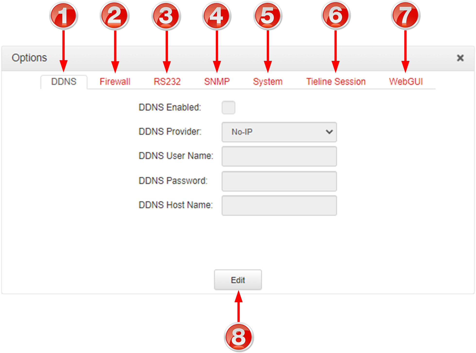
As an example, the Options panel is displayed with a brief description of the other panels available. |
 Settings panels |
|
Feature |
Description |
1 |
Date and Time |
Click to open the panel view and sync the codec to NTP time. |
2 |
Firmware tab |
Click to open the panel; view software versions, download firmware and perform an upgrade. |
3 |
Licensing tab |
Click to open the panel; select a license file and install it in the codec. |
4 |
Options tab |
Click to open the panel and adjust a wide range of codec firewall, RS232, SNMP, system, session data and Web-GUI settings. |
5 |
Reset / Backup |
Click to open the panel; reset codec default settings and perform backup/restore of codec programs and settings. |
6 |
Theme |
Adjust the Theme or 'skin' of the HTML5 Toolbox Web-GUI; options include White or Slate. |
Options panel
|
Feature |
Description |
1 |
DDNS Settings |
Configure Dynamic DNS to use a hostname to connect to a codec when using a dynamic IP address. |
2 |
Firewall Settings |
Enable or disable a range of firewall-related network services, or limit ping to only work in a local subnet. Ember+ can also be enabled. |
3 |
RS232 Settings |
Click Baud rate to adjust the baud rate used by the RS-232 serial port on the codec. Select the check-box to Enable Flow Control. |
4 |
SNMP Settings |
Configure SNMP settings in the codec. |
5 |
System Settings |
Configure various system settings, including: Country setting; select the Lock Loaded User Program check-box to lock the currently loaded program in the codec; enable and assign a hostname to the codec to provide a flexible way of identifying the codec on a network; configure IP audio data packets for expedited or assured forwarding (Quality of Service or QoS) when traversing different networks. |
6 |
Tieline Session |
Edit the Tieline session and alternative session port used by the codec. |
7 |
WebGUI |
Includes settings such as Quick Connect Enabled, CCC Enabled (select this option to enable Cloud Codec Controller use with the codec), enable CSRF, enter a Browser Title, adjust the SSL Port. |
8 |
Edit button |
Press to edit settings in the Options panel. |
Help Panels
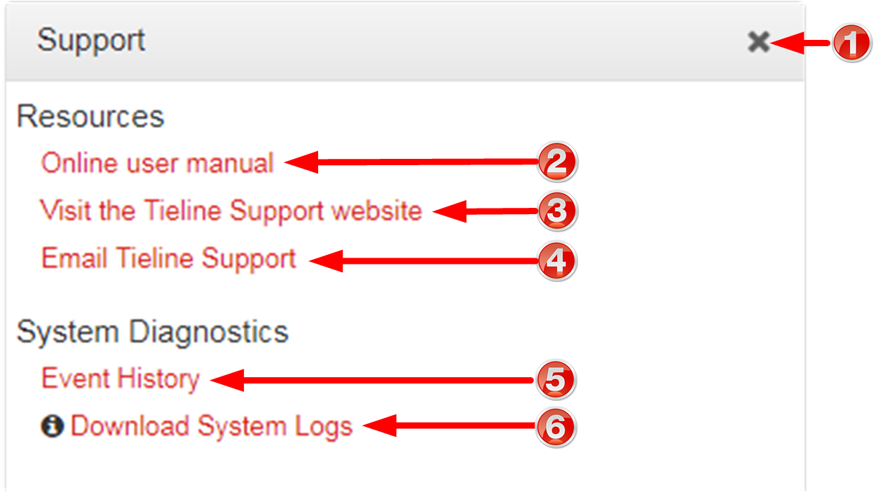
Support Panel
|
Feature |
Description |
1 |
Close button |
Click to close the panel. |
2 |
User manual link |
Click to open the codec user manual in a new browser, or view support information (Note: the codec name displayed will vary by product type) |
3 |
Support website link |
Click to visit the support page on the Tieline website. |
4 |
Email Tieline Support |
Click to email Tieline support. |
5 |
Event History |
Click to download user-viewable event logs |
6 |
Download System Logs |
Click to download diagnostic information that can be sent to Tieline support |
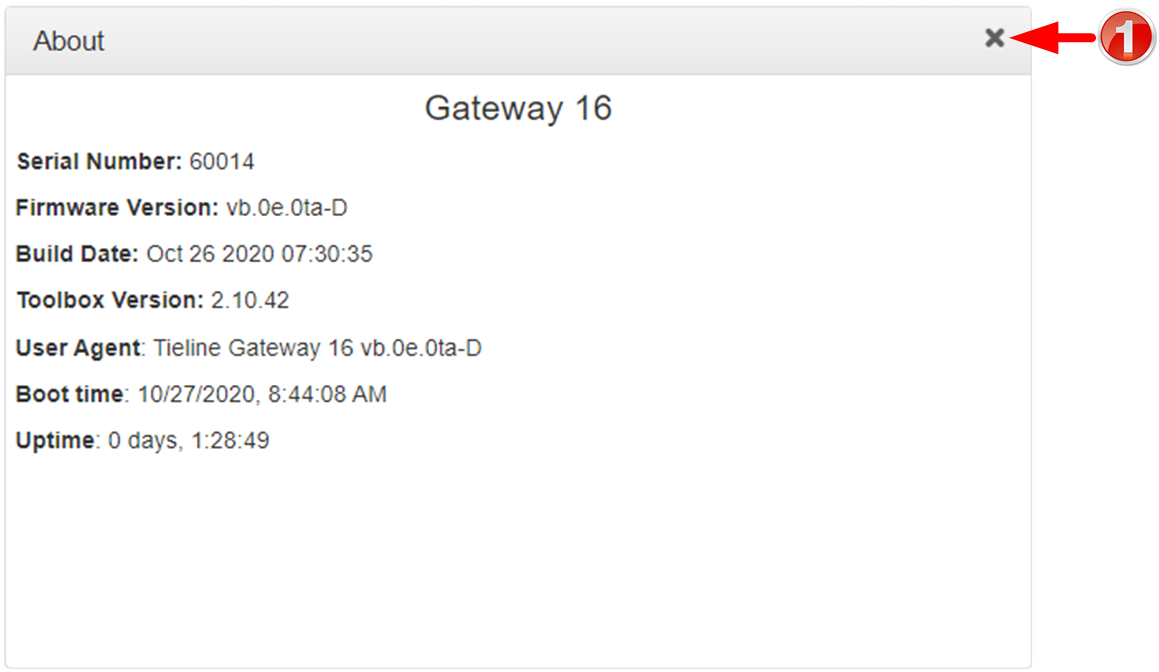
About Panel
Details in this panel displayed include the Toolbox and firmware version, as well as the codec serial number. Note: The codec name displayed varies as per how many channels are enabled in the codec. E.g. An 8 channel codec will display Gateway 8. The following image confirms this is a 16 channel I/O unit named Gateway 16.
|
Feature |
Description |
1 |
Close button |
Click to close the panel. |
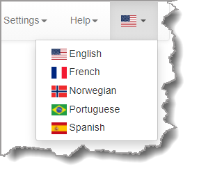
Language Selection
The HTML5 Toolbox Web-GUI offers language support for several languages.
1.Click on the Language drop-down menu arrow in the top right-hand corner of the Web-GUI page.
2.Select the preferred language to display.