Studio IP Streaming Setup for Tieline Audio Codecs
The following instructions are intended to help you configure your internet connection and Tieline codecs at the studio to enable incoming calls over the internet from a remote Tieline codec. It is assumed that you have a basic understanding of your IP network and how to configure IP devices. If you have limited IT network knowledge, we recommend you engage the services of an IT professional to install the public IP address and perform the Network Address Translation (NAT) and port forwarding between the public internet and your private Local Area Network (LAN) at the studio.
Prerequisites
The following procedures are valid for:
•All firmware versions in Gateway and Gateway 4 codecs.
•All firmware versions in the Genie and Merlin codec families.
•All Bridge-IT and Bridge-IT XTRA codecs with firmware release v.2.x or higher.
•All Commander G3 and i-Mix G3 codecs.
Getting Started at the Studio
To perform a typical codec installation at the studio you will need to:
1.Contact your Internet Service Provider and organize a dedicated high speed broadband connection at the studio for your codec with a public static IP address. Do not share this connection with other devices.
2.Install your codec at the studio and attach an active RJ-45 LAN cable to the “LAN” or “Ethernet” port on the rear of the codec. Please note:
•The green LED underneath the “LAN” or "Ethernet" port will illuminate and the orange LED will flash steadily if you are connected to an active LAN connection.
•Many Tieline IP codecs support two simultaneous Ethernet connections.
3.If you are connecting a single codec to a router without a firewall you can enter the public IP address, Subnet Mask and Gateway directly into the codec and your work is done. Note: your Telco should be able to provide this information.
4.Alternatively, if you are connected to a router with a firewall, configure Network Address Translation (NAT) in your router. NAT is performed between the public internet and your private Local Area Network (LAN) by your router. Your remote codec sends IP data packets to the studio router's public static IP address and the router performs NAT, which forwards these data packets to the private IP address allocated by the router to your codec. As part of this process we recommended you:
•Connect to your router using a web-browser.
•Configure it to allocate a static private IP address for each codec.
|
Important Note: The IP address may change if the codec is allocated a DHCP IP address by the router and it loses power or is temporarily disconnected from the LAN. This will cause problems for remote codecs attempting to dial and connect. |

5.Ensure your router's firewall is configured with the relevant TCP and UDP IP ports open to allow data traffic between your codec and the remote codec. The process is fairly simple if you use the following procedure:
a.Connect to your router using a web-browser.
b.Navigate to https://portforward.com/router.htm
c.Select your router manufacturer from the list.
d.Next, select your router model from the list.
e.Follow the instructions to complete port forwarding.
6.Visit www.portforward.com and download the port checking application to verify your router's ports are open, or use a port checker like the one available at https://www.ipfingerprints.com/portscan.php.
7.Configure the static IP address in your codec using the instructions in the next section. To allow multiple codecs to share a single public static IP address behind a firewall and route the calls correctly, your codecs and the firewall need to be configured similarly to the example diagram which follows. Ensure the port, IP address, Subnet Mask and Gateway settings in your codecs match those configured in your router.

Port Forwarding to 3 Studio Codecs Sharing a Public Static IP Address
|
Important Note: •The most common studio configuration issue is a firewall which blocks the incoming and/or outgoing TCP and UDP ports, or not configuring NAT and port forwarding correctly. The following table lists the firewall ports you need to open for each model of Tieline codec if they are dialing your router at the studio. If the remote codec is also connected to a LAN with a firewall you may also need to open the ports at the remote end of the link to connect successfully. •Some firewalls require symmetric port configuration. The codec supports configuration of the "send" audio port (codec port at the remote end of the link to which you are sending audio) and "return" audio port (port used by the local codec to receive audio from the remote codec). |
Firewall Ports |
|
|
||||||||
Commander G3 / i-Mix G3 |
Bridge-IT / Bridge-IT XTRA |
Merlin and Genie Codec Families |
ViA Codec |
Gateway / Gateway 4 Codecs |
Cloud Codec Controller |
|||||
TCP |
UDP |
TCP |
UDP |
TCP |
UDP |
TCP |
UDP |
TCP |
UDP |
TCP |
IP1 Session Port: 9002 |
IP1 Audio Port: 9000 |
Session Port (Sess): 9002 |
Audio (Proto): 9000 |
Session Port: 9002 |
Audio Port Stream 1: 9000 |
Session Port: 9002 |
Audio Port Stream 1: 9000 |
See Table Below |
HTTP 80 |
|
IP2 Session Port: 9012 |
IP2 Audio Port: 9010 |
Web-GUI: 80 |
SIP Session: 5060 |
Alternative Session: 9012 |
Audio Port Stream 2: 9010 |
Alternative Session: 9012 |
Audio Port Stream 2: 9010 |
HTTPS 443 |
||
Toolbox Software: 5550 |
Toolbox Software: 5550 |
Alternative Session: 9012 |
SIP Audio: 5004 |
Web-GUI: 80 |
Audio Port Stream 3: 9020 |
Web-GUI: 80 |
SIP Session: 5060 |
|
||
|
SIP Session: 5060 |
Alternative Web-GUI: 8080 |
Fuse-IP 8999 |
Alternative Web-GUI: 8080 |
Audio Port Stream 4: 9030 |
Alternative Web-GUI: 8080 |
SIP Audio: 5004-5054 |
|
||
|
SIP Audio: 5004 |
TLS/SSL 443 |
|
TLS/SSL 443 |
Audio Port Stream 5: 9040 |
TLS/SSL 443 |
Fuse-IP 8999 |
|
||
|
|
|
|
|
Audio Port Stream 6: 9050 |
|
|
|
||
|
|
|
|
|
SIP Session: 5060 |
|
|
|
SIP Session: 5060 |
|
|
|
|
|
|
SIP Audio: 5004-5054 |
|
|
|
SIP Audio: 5004-5054 |
|
|
|
|
|
|
Fuse-IP 8999 |
|
|
|
Fuse-IP 8999 |
|
Gateway 16 Channel Default Ports
Audio Stream |
TCP Session Port |
UDP Audio Port |
SmartStream + 1 (UDP) |
SmartStream + 2 (UDP) |
SmartStream + 3 (UDP) |
1 |
9002 |
9000 |
9001 |
9002 |
9003 |
2 |
9002 |
9010 |
9011 |
9012 |
9013 |
3 |
9002 |
9020 |
9021 |
9022 |
9023 |
4 |
9002 |
9030 |
9031 |
9032 |
9033 |
5 |
9002 |
9040 |
9041 |
9042 |
9043 |
6 |
9002 |
9050 |
9051 |
9052 |
9053 |
7 |
9002 |
9060 |
9061 |
9062 |
9063 |
8 |
9002 |
9070 |
9071 |
9072 |
9073 |
9 |
9002 |
9080 |
9081 |
9082 |
9083 |
10 |
9002 |
9090 |
9091 |
9092 |
9093 |
11 |
9002 |
9100 |
9101 |
9102 |
9103 |
12 |
9002 |
9110 |
9111 |
9112 |
9113 |
13 |
9002 |
9120 |
9121 |
9122 |
9123 |
14 |
9002 |
9130 |
9131 |
9132 |
9133 |
15 |
9002 |
9140 |
9141 |
9142 |
9143 |
16 |
9002 |
9150 |
9151 |
9152 |
9153 |
Configure a Static IPv4 Address in Gateway and Gateway 4
Static IP addresses are fixed addresses which are recommended for studio installations. Using a static IP address ensures remote codecs can connect reliably using the same IP address over time.
1.Press the SETTINGS  button.
2.Select Transports and press the  button.
3.Use the down ![]() navigation button to select LAN1, LAN2 or a VLAN interface.
navigation button to select LAN1, LAN2 or a VLAN interface.
4.Select Configuration and then Usage and then the appropriate control and/or streaming mode for the connection. Next, press the button.
5.Select IPv4 Mode and press the button.
6.Select Static and press the button.
7.Navigate to IPv4 Address and enter the IP address (using the keypad or onscreen keyboard), then press the button (or select Enter using the onscreen keyboard).
8.Navigate to IPv4 Subnet and enter the Subnet Mask, then press the button.
9.Navigate to IPv4 Gateway and enter the Gateway details, then press the button.
10.Press the Return  button, then select Save in the confirmation dialog and press the button to confirm the new settings.
11.Check the Unit Details menu to ensure the new static IP address has been entered correctly.
Configuring a Static Public or Private IP Address in Genie, Merlin and Bridge-IT (v.2.x firmware) Codecs
1.Press the SETTINGS  button.
2.Select Network and press the  button.
3.Use the down  navigation button to select LAN1, LAN2, Wi-Fi or a VLAN interface.
4.Select Config and then Usage and then the appropriate control and/or streaming mode for the connection. Next, press the button.
5.Select IPv4 Mode and press the button.
6.Select Static and press the button.
7.Navigate to IPv4 Static and enter the IP address, then press the button.
8.Navigate to IPv4 Subnet and enter the Subnet Mask, then press the button.
9.Navigate to IPv4 Gateway and enter the Gateway details, then press the button.
10.Use the up  navigation button to scroll to the top of the menu and select Apply Setting, then press the button to confirm the new settings.
11.Check the Unit Details menu to ensure the new static IP address has been entered correctly.
Configuring a Static IP Address in Commander G3 and i-Mix G3 Codecs
To set up a static IP address in Commander G3 and i-Mix G3 codecs select Menu > Configuration > Advanced > LAN settings > IP Setup > Setup > Static > IP Address > [enter IP address] > press OK > Subnet Mask [enter Subnet Mask] > press OK > Gateway [enter Gateway] > press OK > reboot the codec.
Record IP Address Details
IPv4 Static IP Address |
|
IP Address |
. . . |
Subnet Mask |
. . . |
Default Gateway |
. . . |
IPv6 Mode: Manual |
(Not available in legacy Commander and i-Mix codecs) |
IP Address |
: : : : : : : |
IPv6 Prefix Size |
|
IPv6 Gateway |
: : : : : : : |
Getting Connected
Once the studio codec is configured you are now ready to receive an incoming call from the remote codec over the internet. Always dial from the field codec to the studio codec over the internet unless the remote codec is assigned a public static IP address and you know this address. If you dial the studio using a cell-phone data network at the remote site you will not normally experience any firewall or port blocking issues at the remote end of the link using default Tieline ports.
Troubleshooting: How to Determine Where Firewall Port Blocking is Occurring
If you find you are unable to either send or receive audio between the studio and remote codecs you can use Tieline's Link Quality reading to diagnose where ports are being blocked. LQ can be displayed on the front LCD SCREEN of Tieline's Bridge-IT, Merlin and Genie codecs by selecting Cxns, then select the connection you want to view and press the OK button. LQ readings are also displayed on the home screen of all Commander and i-Mix G3 codecs.
Link Quality (LQ) Readings
Send and Return LQ numbers help you to determine if a problem is occurring at either end of a connection. For example, on an IP connection the Return LQ reading represents the audio being downloaded from the network locally (i.e. audio data is being sent by the remote codec). Conversely, the Send LQ reading represents the audio data being sent by the local codec (i.e. being downloaded by the remote codec). To ensure a stable connection, try to maintain a reliable reading of 80 or higher for both the Send and Return LQ reading.
|
Important Note: •The Return link quality reading is the same as the Local (L) setting displayed on a G3 codec. •The Send link quality reading is the same as the Remote (R) setting displayed on a G3 codec. |
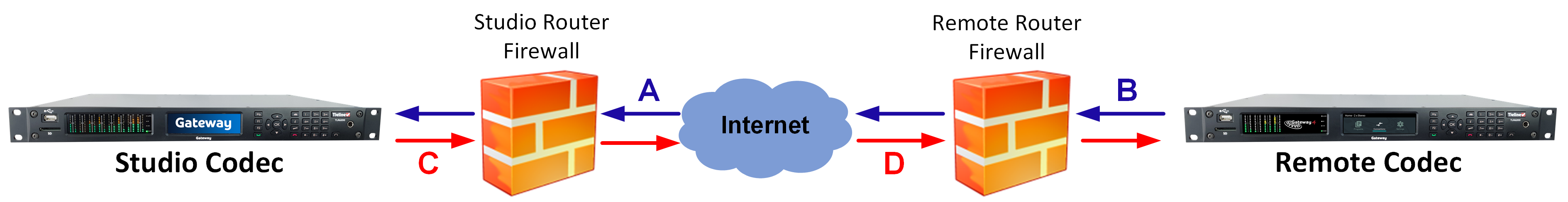
Diagnosing Port Blocking via the Studio Codec LQ
If the studio codec Return LQ reading is 01 then incoming audio from the remote codec is being blocked by a firewall at either point A or B in the following diagram. If the studio codec Send LQ reading is 01 then outgoing audio from the studio is being blocked by a firewall at either point C or D in the following diagram.
Diagnosing Port Blocking via the Remote Codec LQ
If you attach your Tieline codec at the remote site to a LAN with access to the internet you can often dial and connect to the studio without any problem. It is less likely that a firewall will block outgoing TCP and UDP ports. However, if there is a firewall at the remote site it may block incoming data packets from the studio.
The principle is the same at the remote codec for diagnosing blocked ports. If the remote codec Return LQ reading is 01 then incoming audio from the studio codec is being blocked by a firewall at either point C or D in the preceding diagram. If the remote codec Send LQ reading is 01 then the outgoing audio from the remote codec is being blocked by a firewall at either point A or B in the preceding diagram.
Troubleshooting TCP Port Blocking
Error messages on the codec screen can help to diagnose TCP port blocking.
1."Connection Refused" usually means that the firewall is configured correctly but the codec is not using the expected port. For example, the firewall is set up to forward via port 9002 but codec is 'listening' to port 10,000. “Connection Refused” is not normally shown if the firewall is not configured correctly because a firewall will by design silently drop any forwarding requests to ports that it doesn’t have open (see next point). Note: "Connection Refused" will also be displayed if the Commander G3 or i-Mix G3 codec you are calling is already connected.
2.“Connection Timeout” can mean one of two things:
•The firewall is not configured correctly and the attempted codec connection is being silently dropped, e.g. a remote codec is dialing to port 9002 but the studio firewall port forwarding is not configured.
•The UDP port is not port forwarded correctly. Tieline codecs send test data during connection establishment to make sure that the audio path is configured correctly; if this process fails then it will also result in a “Connection Timeout”.
How do I determine which end is blocking data flow?
Tieline test codec firewalls have the default Tieline TCP and UDP ports open. You can dial into these test codecs (or other codecs you know are configured correctly) from your recently configured studio and remote codecs and use the LQ readings to diagnose whether your studio or remote codec firewall is blocking your data packets. If one codec connects ok and the other one doesn't, then you will know which end is likely to be causing the problem. As an example:
1.Dial from site 1 to a Tieline test codec.
2.Dial from site 2 to Tieline test codec.
If both of these connect successfully then the “outbound” TCP path for session data is OK, and the inbound UDP audio path is OK.
3.Dial to site 1 from a codec you know is configured correctly.
4.Dial to site 2 from a codec you know is configured correctly.
If either of these calls fail then TCP and/or UDP inbound data is being blocked on the failed connection (see "Troubleshooting TCP Port Blocking" above).
Testing your Codec
•Visit www.tieline.com or contact Tieline for a list of test IP codec addresses you can use to verify your codec is configured correctly.
•See Testing IP Network Connections for more IP test information.