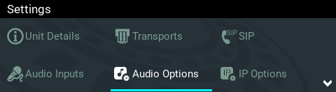
A range of input, output, PPM, synchronization, metering and reference options are configurable within the Audio Options menu.
1.Press the SETTINGS  button.
2.Navigate to Audio Options and press the  button.
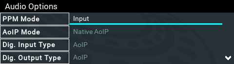
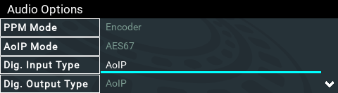
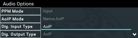
PPM Mode
PPM metering can be adjusted to display input, output, encoder and decoder PPMs. This is adjusted via Settings > Audio Options > PPM Mode. Gateway has 16 PPM meters and between 8 and 16 inputs depending on the configuration purchased; encoders and decoders available will match input availability/configuration. The Gateway 8 also supports Input/Output and Encoder/Decoder modes, whereby all 16 PPMs can be used to simultaneously monitor up to 8 inputs and outputs, or up to 8 encoders and decoders.
Gateway 4 has 4 inputs, 4 outputs, 4 encoders, 4 decoders, and 8 PPMs only. The Gateway 4 also supports Input/Output and Encoder/Decoder modes with reduced channel capability. See Input Configuration, Levels and PPMs for more details.
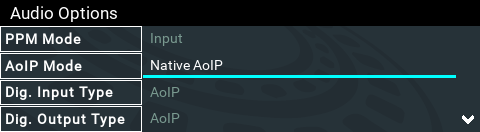
AoIP Mode
AoIP streaming is natively supported and this setting selects whether the codec will stream using native AoIP protocols (e.g. AES67, ST 2110-30, Livewire+, RAVENNA) or WheatNet-IP when an optional WheatNet-IP card is installed.
1.Press the SETTINGS button.
2.Navigate to Audio Options and press the button.
3.Select AoIP Mode.
4.Select the correct mode of operation.

Digital Input Type
The codec supports configuration of all inputs as digital AES3, or digital AoIP inputs.
1.Press the SETTINGS button.
2.Navigate to Audio Options and press the button.
3.Select Dig. Input Type.

Digital Output Type
The codec supports configuration of all outputs as digital AES3, or digital AoIP outputs.
1.Press the SETTINGS button.
2.Navigate to Audio Options and press the button.
3.Select Dig. Output Type.

AES3 Out Clock Source
The codec contains two sample rate converters.
Input Sample Rate Converter
The codec implements an Asynchronous Sample Rate Converter (ASRC) to convert the sample rate of an AES3 input to the sample rate set in the codec. The codec sample rate is determined by the selected algorithm. For example, if you select the Music algorithm, the sample rate will be set to 32kHz. By default the codec will up-sample all AES3 input sources to 96kHz sampling and then convert to match the AES output sample rate setting.
|
Important Note: All AES3 inputs must have the same sample-rates and must be synchronized to a common clock. See Appendix B for pin-outs of AES3 inputs. |

Output Sample Rate Converter
The sample rate of the AES3 output is configured using the clock source setting via the SETTINGS button and then Audio Options > AES3 Out Clock Src. This configures the sample rate frequency of all AES3 output signals.
Wordclock Sync In
This setting configures the codec for a word clock source via the SYNC I/O 2 BNC connector on the codec rear panel (this is the same as the External Word Clock setting in Tieline G3 codecs). Often this will be a studio reference signal. In television broadcasting facilities the audio reference signal should be locked to the video reference if there is one available. The sample rate being received is recognized by the codec and automatically adjusted. Supported sample rates include 32 kHz, 44.1 kHz, 48 kHz and 96 kHz. Note: The reference clock must be within +/- 50ppm of the listed sample rates.
Lock to AES3 Input
With this setting the codec uses AES3 input sync information to set the codec output sample rate (Note: this is the same as the AES Rx Clock setting in Tieline G3 codecs). The codec initially tries to use the signal on AES inputs 1 and 2 as the clock to which the AES outputs are synchronized. If unavailable, it then attempt to use inputs 3 and 4, or inputs 5 and 6 and so on in that order. If you select this option, all AES inputs must always be synchronized to the same clock source, e.g. if AES3 inputs 1 and 2 use 48kHz sampling then all other inputs must also be synchronized to the same clock. Supported sample rates include 32 kHz, 44.1 kHz, 48 kHz and 96 kHz. Note: The reference clock must be within +/- 50ppm of the listed sample rates.
Lock to AES11 Input
AES11 is a standard AES3 signal with an accurate clock reference (DARS, or Digital Audio Reference Signal), usually without the audio data. To use this input attach a female BNC connector to the SYNC I/O 1 connector on the codec rear panel. Supported sample rates include 32 kHz, 44.1 kHz, 48 kHz and 96 kHz. Note: The reference clock must be within +/- 50ppm of the listed sample rates.
Fixed Sample Clock
Select from a range of fixed output sample rates including:
1.32 kHz
2.44.1 kHz
3.48 kHz
4.88.2 kHz
5.96 kHz
6.192 kHz
Note: The reference clock must be within +/- 50ppm of the listed sample rates.
Reference Level
The default Tieline G6 audio reference scale displayed on the PPMs when connecting to a Tieline G6 codec is -40dBFS to 0dBFS. Using this reference scale audio peaks can safely reach 0dBFS without clipping, providing 20dB of headroom from the nominal 0vu point. The comparison table below outlines the reference scales for G6, G5, G3 codecs and Report-IT in dBFS, as well as the equivalent dBU scale.
|
Reference Level |
Description |
dBu |
dBFS |
1 |
Tieline G6 (Gateway) |
PPM meter low point |
-16dBU |
-40dBFS |
Nominal 0vu reference level |
+4dBU |
-20dBFS |
||
Level at which audio will clip/distort |
+24dBu |
0dBFS |
||
2 |
Tieline G5 (Genie, Merlin, Bridge-IT) |
PPM meter low point |
-16dBu |
-38dBFS |
Nominal 0vu reference level |
+4dBu |
-18dBFS |
||
Level at which audio will clip/distort |
+22dBu |
0dBFS |
||
3 |
Tieline G3 (Commanderand i-Mix) |
PPM meter low point |
-11dBu |
-29dBFS |
Nominal 0vu reference level |
+4dBu |
-14dBFS |
||
Level at which audio will clip/distort |
+18dBu |
0dBFS |
||
4 |
Report-IT |
PPM meter low point |
-9dBu |
-23dBFS |
Nominal 0vu reference level |
+4dBu |
-10dBFS |
||
Level at which audio will clip/distort |
+14dBu |
0dBFS |
The default setting in the codec is Auto. To reconfigure this:
1.Press the SETTINGS button.
2.Navigate to Audio Options and press the button.
3.Select Reference Level.
|
Important Note: If a codec supports multiple stream programs and the Auto (default) reference level is selected, the first codec to connect will configure the reference level used for all subsequent connections. I.e. If a G5 codec connects first then the G5 Audio Reference Level will be configured for all connections. |

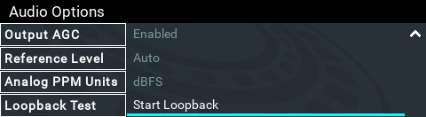
Analog PPM Units
It is possible to switch the analog input PPM meter unit of measurement from dBFS (default) to dBU:
1.Press the SETTINGS button.
2.Navigate to Audio Options and press the button.
3.Select Analog PPM Units.
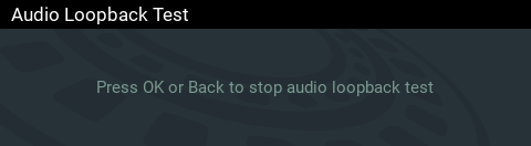
Loopback Test
Test mode is used by the codec to perform an input/output loopback test of audio. E.g. Input 1 is routed to Output 1, Input 2 is routed to Output 2 etc.
1.Press the SETTINGS button.
2.Navigate to Audio Options and press the button.
3.Select Start Loopback and press the button for Loopback Test.
4.Press or the Return  button to end the loopback test.